Columnar downhole gas separator and method of use

a gas separator and column technology, applied in the field of gas separators, can solve the problems of addition of gas bubbles to the fluid, and achieve the effects of reducing the amount of gas bubbles, less chance of locking up, and efficient operation

Inactive Publication Date: 2010-06-17
SWARINGIN RON
View PDF29 Cites 19 Cited by
  • Summary
  • Abstract
  • Description
  • Claims
  • Application Information

AI Technical Summary

Benefits of technology

[0009]The present invention addresses the need to separate mixed fluid in a production well into gas and a gas bubble free fluid. The present invention reduces the amount of gas that remains in a fluid when it reaches the pump. Reduction of gas enables the pump to operate more efficiently without locking-up. In addition, the present invention enables the gas separator to remain in the production well for a longer period of time. Often, the fluid in a production well contains silt and heavy particles that separate from the fluid as it is pumped to the surface. The portion of the production pipe that extends below the gas separator allows the sediment to gather in the lower portion of the production pipe without blocking or “silting-in” the perforations that allow fluid flow.
[0011]The present invention attaches to a string of production pipe that is lowered down a well. The gas separator is attached at some point in the middle of the string of production pipe, so that some of the production pipe extends below the gas separator. A section of production pipe that is covered by the gas separator is perforated. The fluid in the well is a mixed fluid that consists of fluid and gas bubbles. Initially, the mixed fluid rises in the well. Some gas bubbles continue to rise and are separated as the fluid changes direction and enters the open top of the gas separator. Gravity continues to act on the fluid causing further gas bubble separation as the mixed fluid is drawn down the length of the gas separator. The perforations in the production pipe cause the velocity of the fluid to increase, resulting in additional separation of gas bubbles from the fluid. The fluid, which has been separated from some gas bubbles, gathers in the production pipe. As this fluid continues downward to the opening of the gas anchor, gravity continues to operate, separating additional gas bubbles. As the additional bubbles separate, they rise and exit through the perforations in the production tubing and ultimately the open top of the gas separator. Thus, the fluid that enters the gas anchor and is ultimately pumped to the surface has a greatly reduced amount of gas bubbles. This allows the pump to operate more efficiently, with less chance of locking-up due to a gas pocket in the pump.

Problems solved by technology

The perforations in the production pipe cause the velocity of the fluid to increase, resulting in additional separation of gas bubbles from the fluid.

Method used


Image

  • Columnar downhole gas separator and method of use
  • Columnar downhole gas separator and method of use
  • Columnar downhole gas separator and method of use

Examples


Embodiment Construction

[0018]In the descriptions that follow, like parts are marked throughout the specification and drawings with the same numerals, respectively. The drawing figures are not necessarily drawn to scale and certain figures may be shown in exaggerated or generalized form in the interest of clarity and conciseness.

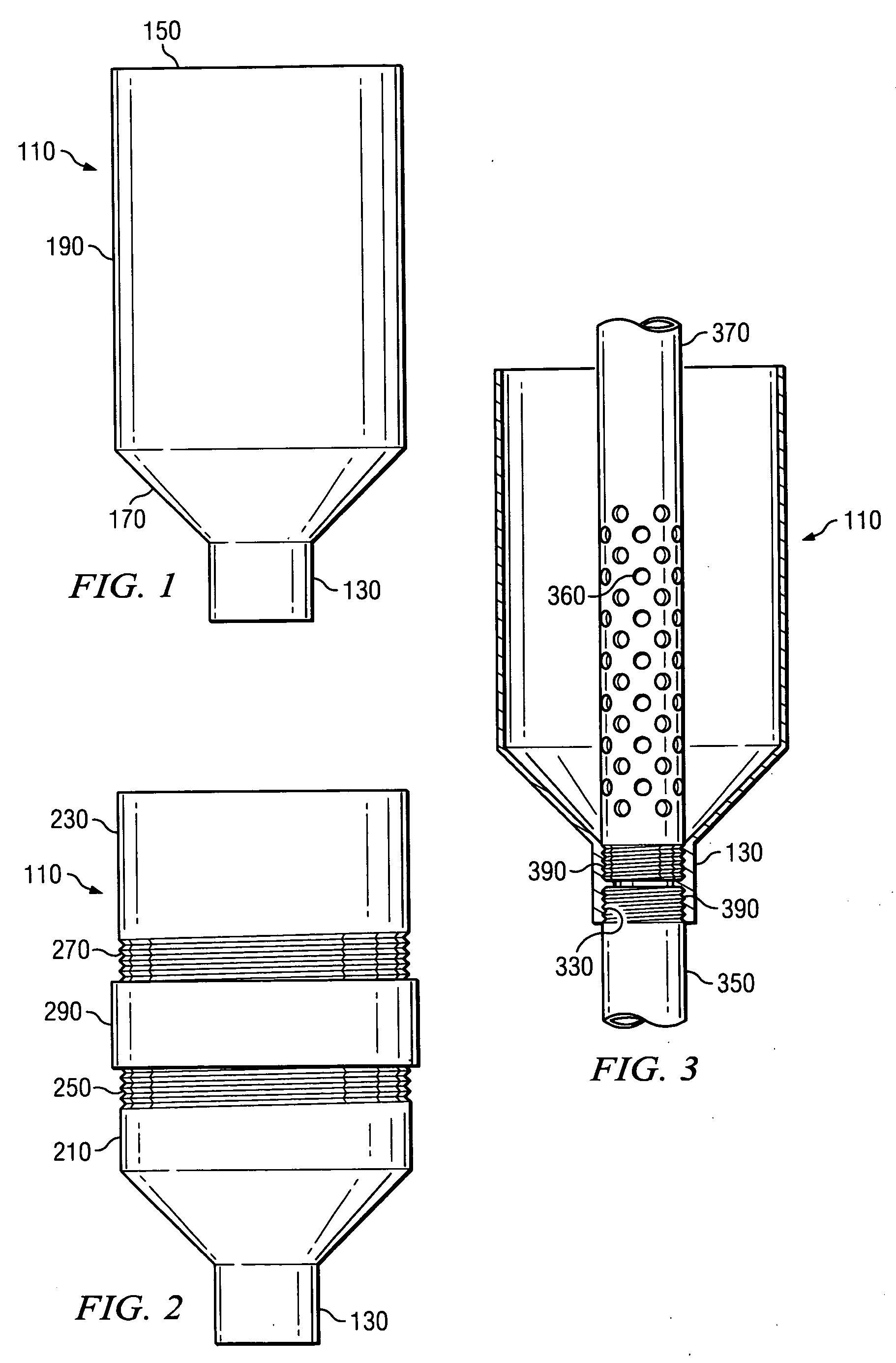
[0019]With Respect to FIG. 1, gas separator 110 is supported by a bell collar 130. Bell collar 130 is a cylindrical shape designed to support the gas separator by attaching to production pipe (not shown). Taper 170 is an angle between the bell collar 130 and the shroud 190. Shroud 190 causes mixed fluid to enter the gas separator 110 through the top opening 150 of the gas separator 110.

[0020]FIG. 2 shows the preferred embodiment of gas separator 110. Gas separator 110 consists of three pieces; a bell section 210, a collar 290, and a shroud 230. Shroud 230 has external threads 270. Additionally, the bell section 210 has bell collar 130. Bell collar 130 attaches to production pipe (n...


PUM


Abstract

A gas separator is provided including a tapered portion, the “bell section” and a wide portion, the “shroud.” The bell section resides on the lower end of the gas separator where it attaches to the production pipe. The shroud is substantially larger in diameter than the production pipe and allows mixed fluid and gas to enter through an open top.The gas separator is attached at the string of production pipe, so that some of the production pipe extends below the gas separator. A section of production pipe that is covered by the gas separator is perforated. Gas bubbles are removed from the mixed fluid by gravity, abrupt changes in direction, and perforations that restrict the flow area of the fluid.

Description

FIELD OF THE INVENTION[0001]This invention relates generally to gas separators. More particularly, the invention relates to gas separators suspended above the bottom of a production well and used to separate mixed fluid that consists of gas bubbles suspended in liquid.BACKGROUND OF THE INVENTION[0002]Generally, fluid produced from a well must be pumped to the surface. Most of these fluids are mixed, consisting of gas bubbles suspended within the fluid. Gas passing through a pump reduces the efficiency of the pump and increases the cost to produce the fluid from the well. In extreme circumstances, large quantities of gas can create “gas lock” within the pump. “Gas lock” prevents fluid from being displaced, effectively stopping production and potentially damaging the pump. Therefore, it is considered desirable to separate the gas from the fluid. Pumping fluid substantially free from gas prevents the aforementioned problems and results in lower production costs.[0003]Separation of gas ...

Claims


Application Information

Patent Timeline
Patent Type & Authority Applications(United States)
IPC IPC(8): E21B43/38E21B43/34
CPCE21B43/38
Inventor SWARINGIN, RON
Owner SWARINGIN RON
Why Eureka
Try Eureka