Fitting cover

a technology for fittings and protective caps, applied in the direction of lubricant filling/draining, conduits/junctions, lubrication elements, etc., can solve the problems of equipment failure, additional time cleaning grease fittings, maintenance personnel consuming substantial time locating fittings

Inactive Publication Date: 2010-06-17
WHITMORE MFG LLC
View PDF13 Cites 8 Cited by
  • Summary
  • Abstract
  • Description
  • Claims
  • Application Information

AI Technical Summary

Problems solved by technology

Often, such fittings are positioned in places that are difficult to locate and are exposed to conditions and foreign materials that may damage the fittings or the machinery that uses the fittings.
Under such conditions, equipment failure may result.
Therefore, maintenance personnel consume substantial time locating fittings hidden by dust and dirt, and additional time cleaning the grease fittings before the grease gun is attached.
An incorrect lubricant can result in catastrophic machine failure.
However, such covers suffer a variety of deficiencies.
Typically, the covers are small and difficult to locate, especially when covered in dust or when installed in poorly lit areas.
However, the covers are only available in a limited range of colors and usually fade.
In addition, the covers do not provide adequate grip for removing the covers from the fittings, making it difficult to inject new lubricants into the machine.
Typically, the covers provide no indication of the correct lubricant to inject into the machine.

Method used


Image

  • Fitting cover
  • Fitting cover
  • Fitting cover

Examples


Embodiment Construction

[0021]While the invention is described with reference to lubricant fittings, it should be clear that the invention should not be limited to such uses or embodiments. The description herein is merely illustrative of an embodiment of the invention and in no way should limit the scope of the invention.

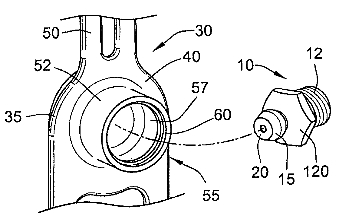
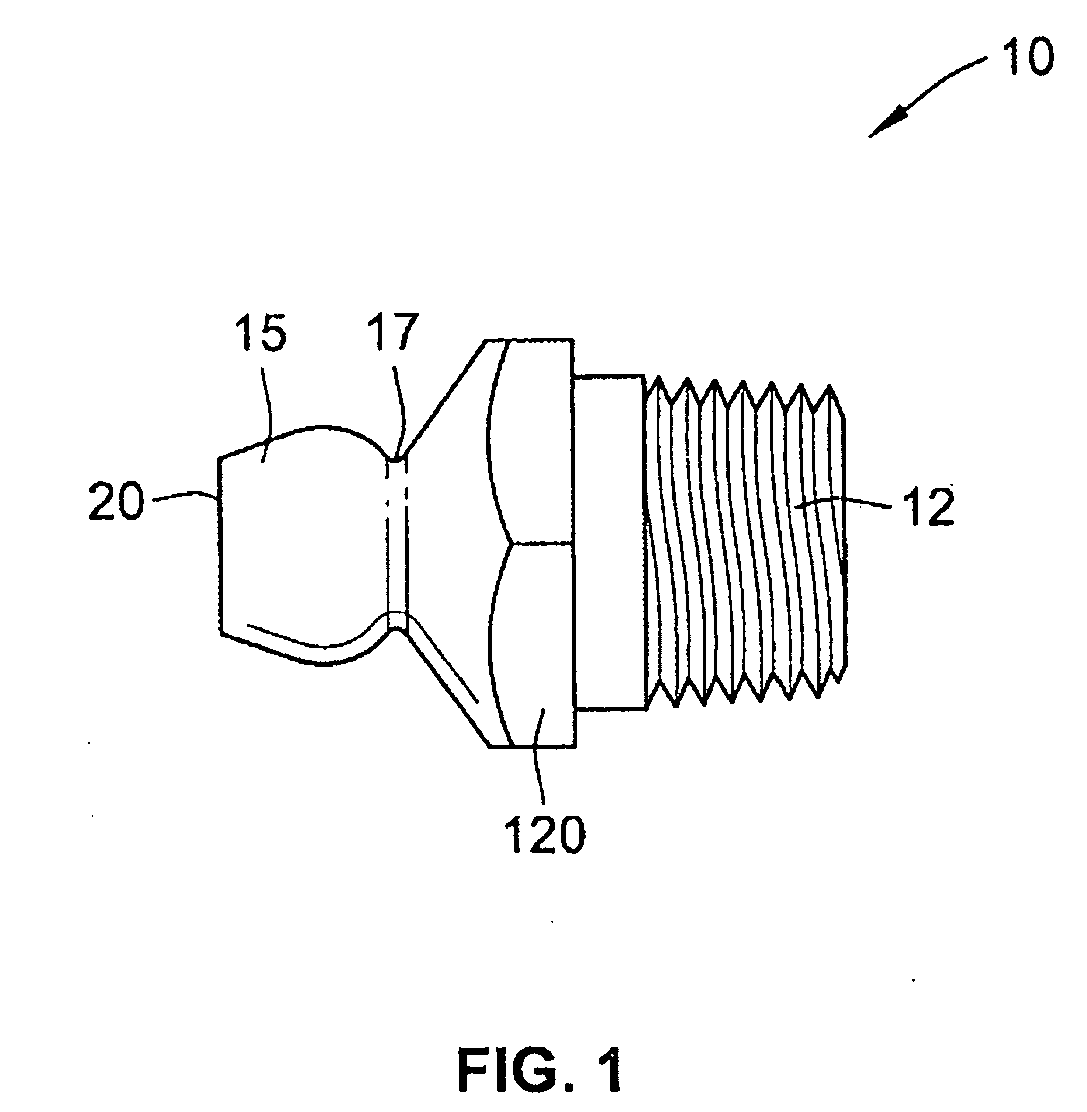
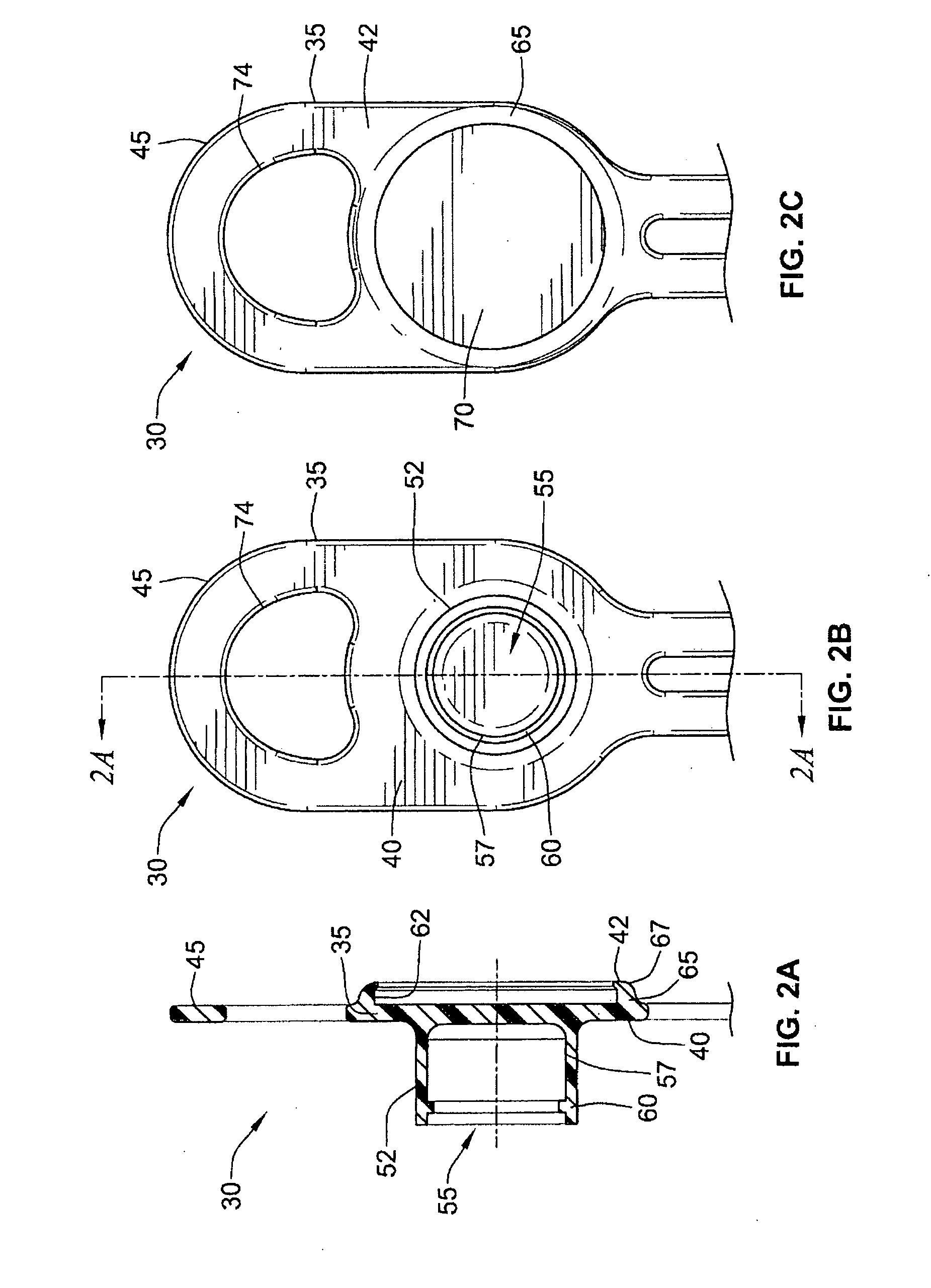
[0022]Reference will now be made to an embodiment of the invention as illustrated in accompanying FIGS. 2-9. As shown in FIG. 2A, a cover 30 is provided having a body 35 with a first side 40 and a second side 42. The first side 40 is capable of being removeably secured to the head 15 of a fitting 10. The second side 42 includes an indicator 85 providing information, such as, the type of lubricant to be injected through the fitting 10. As shown in FIGS. 3A, 3B, and 3C, the cover 30 may have a grip 45, a retaining member 47, and legs 50.

[0023]As shown in FIGS. 2A and 2B, the body 35 may be substantially planar and may be made from a variety of materials including, but not limited to, metals...


PUM


Abstract

A lubricant fitting cover for a zerk having a substantially planar body with a first side and a second side, the first side is capable of being removeably secured to the head of a grease fitting, the second side includes an indicator for providing information about the type of lubricant to be injected through the grease fitting.

Description

FIELD OF INVENTION[0001]The present invention generally relates to a protective cap for fittings. More specifically, the present invention relates to an improved protective cap for a lubricant fitting.BACKGROUND OF THE INVENTION[0002]Generally, machinery is provided with lubricant fittings such as a nipple or zerk to apply internal lubrication. The fittings allow lubricants, such as grease, to be injected under pressure into the machine, while preventing such lubricant from leaking outwardly therefrom. As shown in FIG. 1, a typical lubricant fitting 10 has a wrenching surface 120 and a threaded end 12 for securing to a port of a machine. The opposite end of the fitting 10 generally includes a head 15 having a neck 17 and lubricant introduction port 20 with a check valve (not shown). To apply lubrication, a grease gun may be secured to the head 15 to inject the lubrication into the port 20 with sufficient force to overcome the check valve and the internal pressure of the machine.[000...

Claims


Application Information

Patent Timeline
Patent Type & Authority Applications(United States)
IPC IPC(8): F16N21/06
CPCF16N21/06F16N21/02
Inventor JOSS, MICHAEL S.KILIAN, TONY CHRISTERKILIAN, MICHAEL TONY
Owner WHITMORE MFG LLC
Why Eureka
Try Eureka