Thermal imaging camera for taking thermographic images

a thermographic image and imaging camera technology, applied in the field of thermographic imaging cameras, can solve the problems of high manufacturing cos

Inactive Publication Date: 2010-06-17
TESTO AG
View PDF9 Cites 39 Cited by
  • Summary
  • Abstract
  • Description
  • Claims
  • Application Information

AI Technical Summary

Problems solved by technology

Since a high maximum possible resolution gives rise to high manufacturing costs, especially, for the detector field of the thermal imaging camera, one makes due by, optionally with a wide-angle lens, first taking an overall pict

Method used


Image

  • Thermal imaging camera for taking thermographic images
  • Thermal imaging camera for taking thermographic images
  • Thermal imaging camera for taking thermographic images

Examples


Embodiment Construction

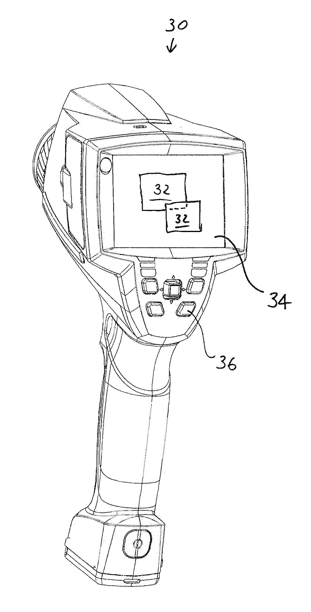
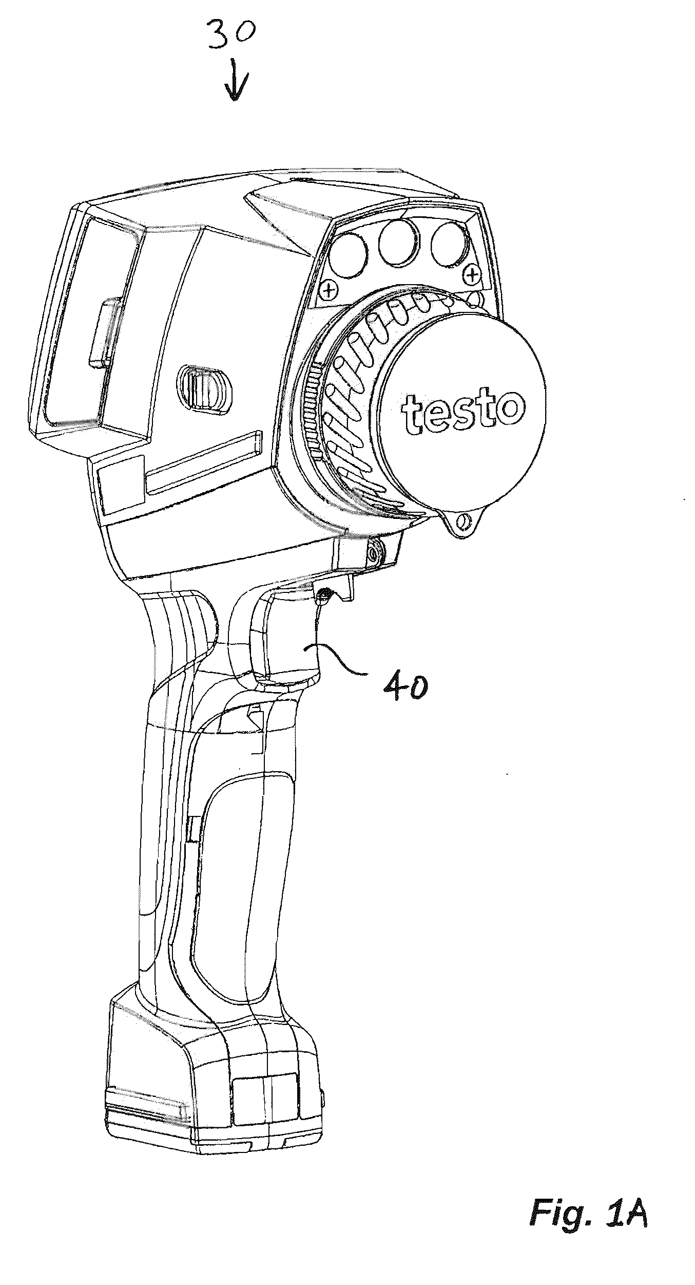
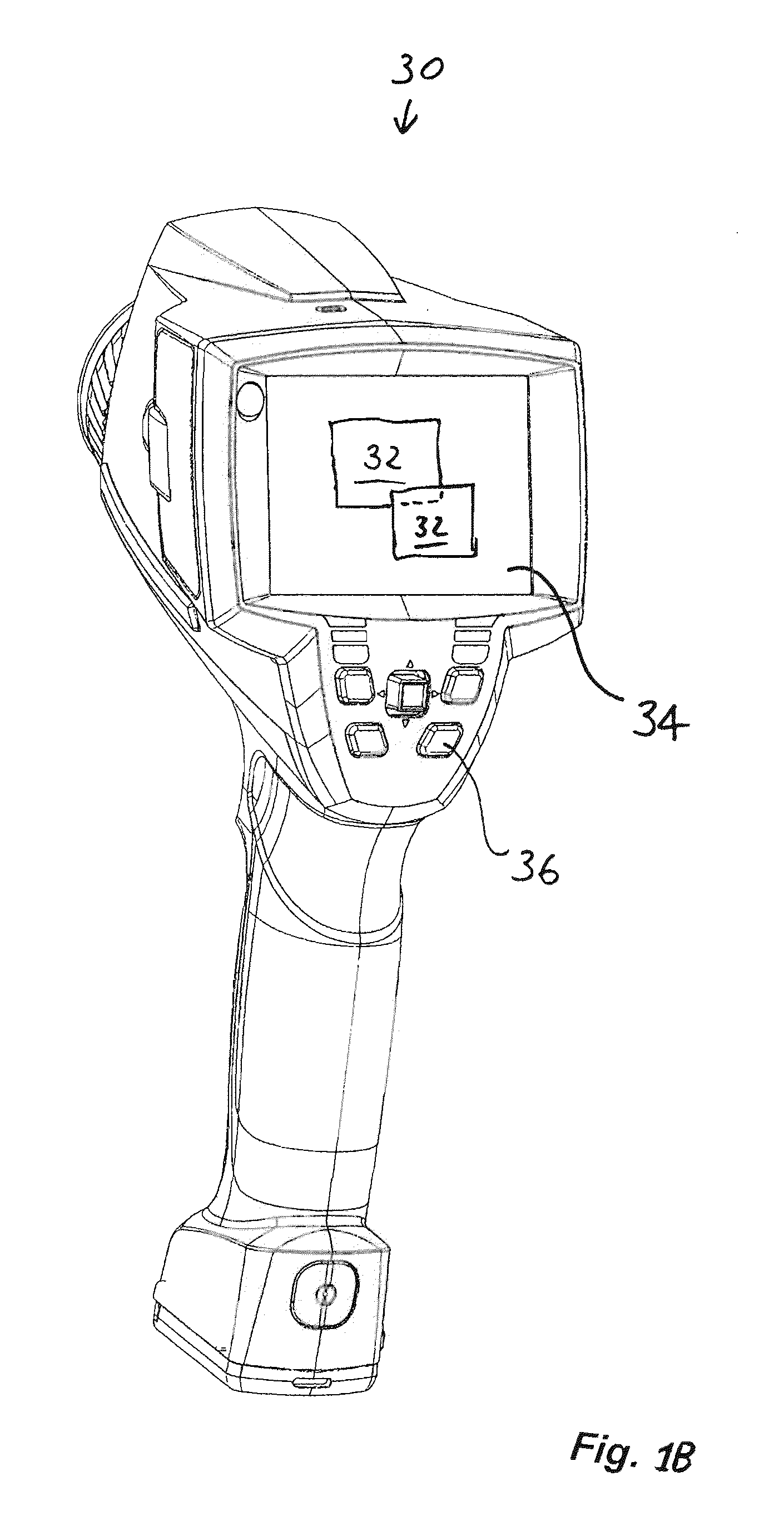
[0017]The invention is based on the task of creating a thermal imaging camera that enables the acquisition and display of large solid angle regions with high resolution. FIGS. 1A and 1B provide an example of a thermal imaging camera 30 for use with the invention provided herein.

[0018]To solve this problem it is provided that an electronic evaluation unit 80 is integrated into the thermal imaging camera 30 of the kind mentioned at the start, with which at least an acquired thermographic image 32 can be stitched with another acquired thermographic image 32 or a stored thermographic image in the edge regions, where the images each repeat the same section of the measurement object in said edge region, to form a new thermographic overall image and can be provided for combined display with the display tool 34, where the display tool 34 has a zoom function 36 for free selection of a segment of the overall image that is to be enlarged. Thus, the measurement object specifies a solid angle re...


PUM


Abstract

In a thermal imaging camera for acquisition of thermographic images of a measurement object, an electronic evaluation unit is integrated into the thermal imaging camera; it is designed for recognition of corresponding partial regions of the acquired thermographic images, and with it, the acquired images can be assembled into an overall image by overlapping the corresponding partial regions and displayed. The acquisition of the images preferably takes place during the swiveling of the thermal imaging camera over the solid angle region of the desired overall image.

Description

TECHNICAL FIELD[0001]The invention concerns a thermal imaging camera for taking thermographic images of a measurement object in the infrared region with an indicator tool built in or on the housing for a representation of the taken thermographic images, where the thermal imaging camera is made as a hand-held unit. The representation of the thermographic images may use any kind of color mapping, e.g. false color representation, grey tone representation, and the like.[0002]The invention additionally concerns a method for generating a thermographic image of a large measurement object.DESCRIPTION OF THE PRIOR ART[0003]A system for dual band acquisition of infrared images in which the IR images acquired in two spectral bands are combined into an image by overlapping by means of image processing in a computer system is known from the publication of M. Muller et al.: “Real-time image processing and fusion for a new high-speed dual-band infrared camera.”[0004]A digital photo apparatus for t...

Claims


Application Information

Patent Timeline
IPC IPC(8): G01J5/30H01L31/09
CPCH04N5/232H04N5/23238H04N5/23293H04N5/23296G01J2005/0077H04N5/332H04N5/33H04N23/698H04N23/69H04N23/63H04N23/11
Inventor STRATMANN, MARTINMESSERSCHMID, ANDREASZAHN, PATRICK
Owner TESTO AG
Why Eureka
Try Eureka