Fluid dynamic bearing system

a dynamic bearing and fluid technology, applied in the direction of sliding contact bearings, mechanical energy handling, mechanical equipment, etc., can solve the problems of high cost of manufacture, inconvenient operation, and inability to operate at high rotational speeds over a longer period, so as to achieve high rotational speeds, low noise generation, and easy and cheap construction

Inactive Publication Date: 2010-06-17
MINEBEA CO LTD
View PDF34 Cites 7 Cited by
  • Summary
  • Abstract
  • Description
  • Claims
  • Application Information

AI Technical Summary

Benefits of technology

[0005]It is the object of the invention to provide a fluid dynamic bearing system that can be easily and cheaply constructed but nevertheless allows operation at high rotational speeds and ensures low noise generation.

Problems solved by technology

Electric motors having fluid dynamic bearing systems are very often constructed in an extremely complicated way and are expensive to manufacture, as, for example, the spindle motor having a fluid dynamic bearing according to U.S. Pat. No. 7,015,611 B2.
The bearing system shown here can be easily and cheaply constructed, but because the axial bearing employed is subject to friction, the bearing system is not suitable for operation at high rotational speeds over a longer period of time, rotational speeds in the range of 10,000 rpm and over being applicable here, as required nowadays in such precision motors.
However, due to the relatively simple method of sealing the bearing gap in the region between the shaft and an upper covering plate, this bearing is not intended for high rotational speeds.

Method used


Image

  • Fluid dynamic bearing system
  • Fluid dynamic bearing system
  • Fluid dynamic bearing system

Examples


Embodiment Construction

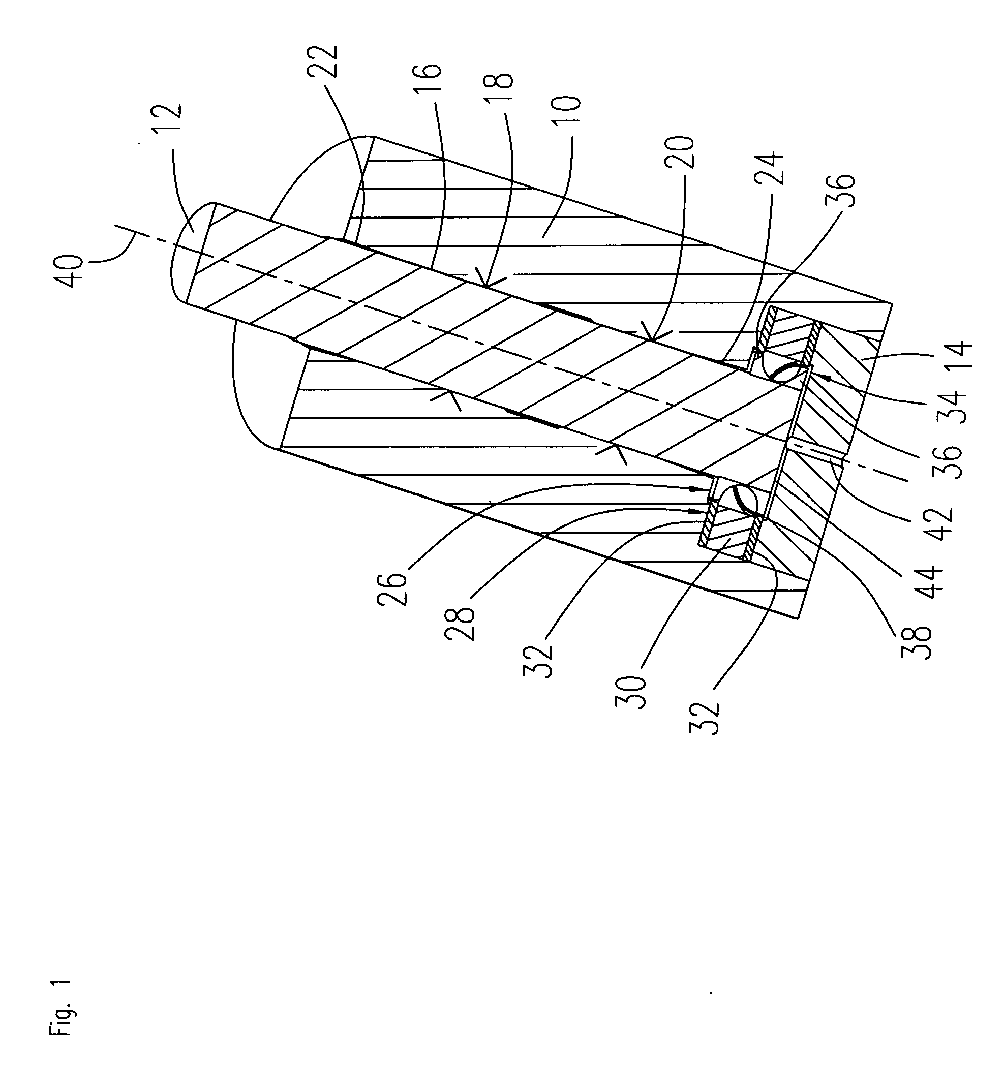
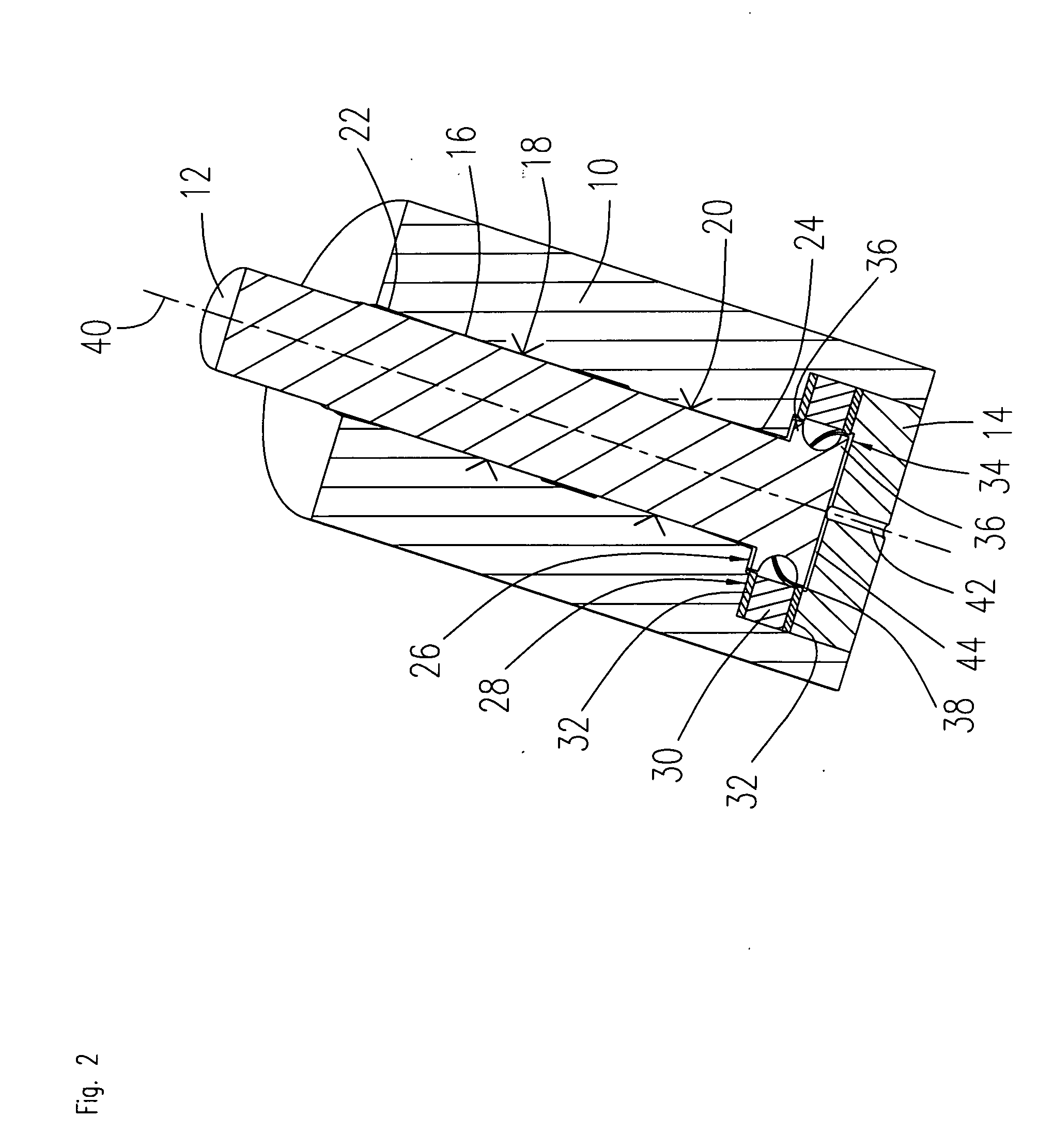
[0032]FIG. 1 shows a section through a first embodiment of a bearing according to the invention. The bearing consists of a bearing bush 10 that is given a substantially cylindrical shape and comprises a central bearing bore. At one end of the bearing bush 10, the central bearing bore widens out and forms a cylindrical recess having a larger diameter. A cylindrical shaft 12 is rotatably supported in the bore in the bearing bush 10, the outside diameter of the shaft 12 being slightly smaller than the inside diameter of the bearing bore. A bearing gap 16 filled with a bearing fluid thus remains between the outside diameter of the shaft 12 and the inside diameter of the bearing bush 10. The bearing gap 16 is open at both ends and each end is sealed against the environment by a sealing gap 22, 24. The sealing gaps 22, 24 are preferably formed as capillary seals and proportionally filled with bearing fluid. The sealing gaps 112, 14 moreover form a reservoir and expansion volume for the be...


PUM


Abstract

The fluid dynamic bearing system according to the invention for the rotatable support of an electric motor comprises a substantially cylindrical bearing bush having a bearing bore, a shaft rotatably supported about a rotational axis accommodated in the bearing bore, a bearing gap formed between mutually adjacent surfaces of the bearing bush and the shaft that is filled with a bearing fluid and extends in an axial direction parallel to the rotational axis, at least one radial bearing that is disposed along the bearing gap and formed by bearing surfaces of the bearing bush and the shaft, and at least one axial bearing that is formed as a magnetic bearing.

Description

BACKGROUND OF THE INVENTION[0001]The invention relates to a fluid dynamic bearing system for the rotatable support of an electric motor, preferably a spindle motor, as can be used, for example, for driving hard disk drives, ventilators or pumps.PRIOR ART[0002]Electric motors having a fluid dynamic bearing system are known in the prior art in a large variety of designs. In particular, drive motors for hard disk drives, optical storage drives as well as ventilators have to ensure a high rotational speed at great precision and at the same time have low noise generation and allow cheap manufacture in large numbers. Over the last few years, fluid dynamic bearing systems have proven to be the primary choice when it comes to the rotatable support of these kinds of electric motors. Electric motors having fluid dynamic bearing systems are very often constructed in an extremely complicated way and are expensive to manufacture, as, for example, the spindle motor having a fluid dynamic bearing ...

Claims


Application Information

Patent Timeline
Patent Type & Authority Applications(United States)
IPC IPC(8): H02K9/00F16C32/06H02K7/09H02K5/167
CPCF16C17/026F16C32/0402H02K7/09H02K7/085F16C32/0417
Inventor BAUER, MARTINPOPOV, VLADIMIR V.SCHMID, GUIDO
Owner MINEBEA CO LTD
Why Eureka
Try Eureka