Riding lawn mower
a lawn mower and riding technology, applied in the direction of fluid gearing, transportation and packaging, gearing, etc., can solve the problems of increasing the manufacturing cost of linkages and the space for disposal thereof in the vehicle, difficult to control the vehicle, and long time-consuming equalization during the operation of the vehicle, so as to reduce the risk of sudden turning, reduce the risk of collision, and reduce the effect of collision
- Summary
- Abstract
- Description
- Claims
- Application Information
AI Technical Summary
Benefits of technology
Problems solved by technology
Method used
Image
Examples
first embodiment
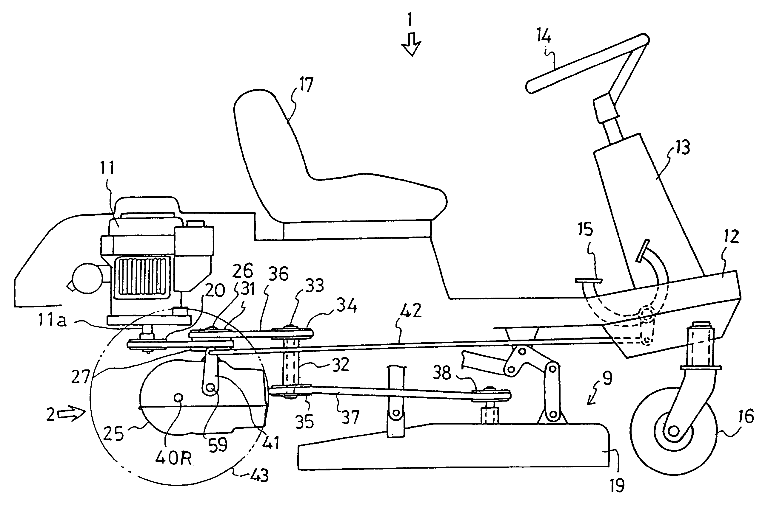
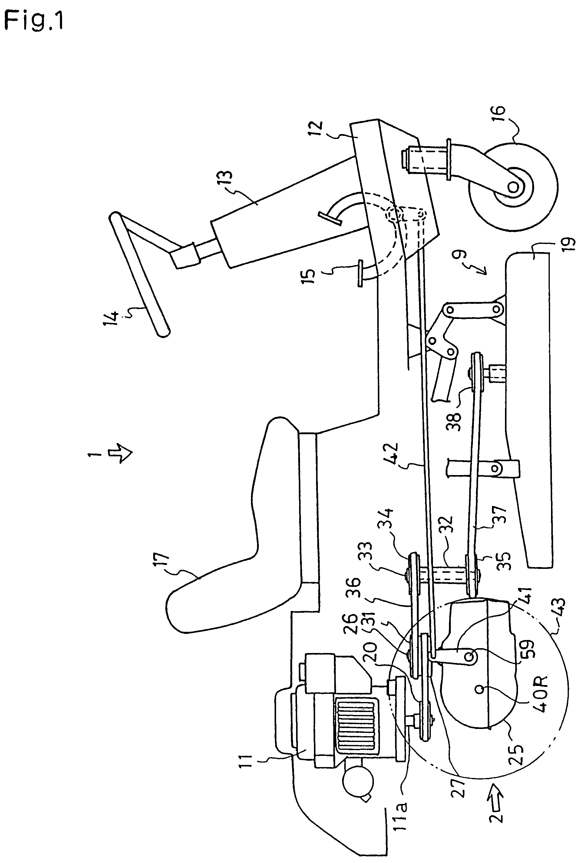
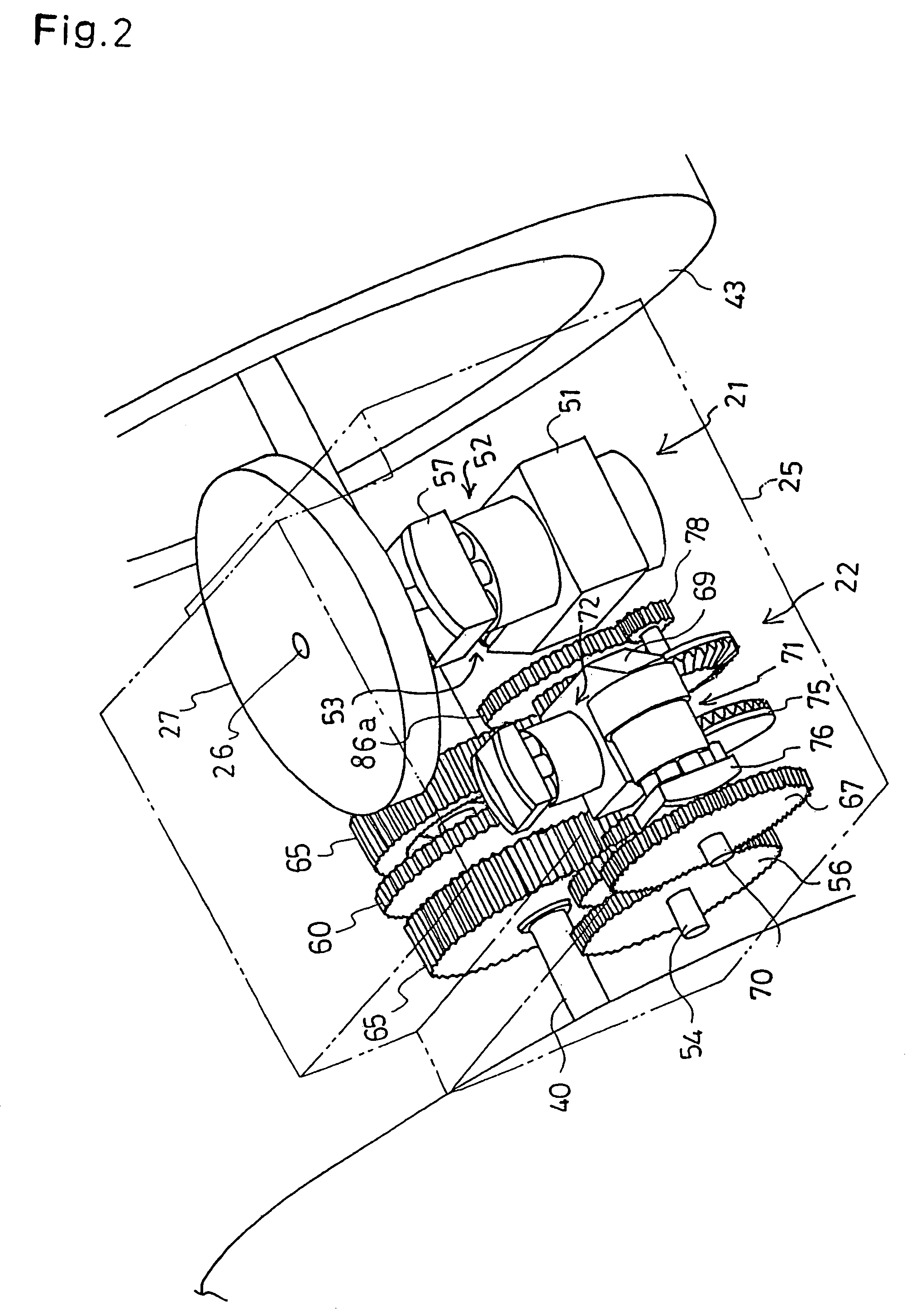
[0059]Next, referring to FIGS. 2, 3 and 4, the internal mechanism of housing 25 as transmission 2 comprising HSTs 21 and 22 and differentials 24 and 23 will be described in accordance with the present invention.
[0060]First HST 21 for speed change in traveling is a well-known combination of a variable capacity type hydraulic pump 52 and a fixed capacity type hydraulic motor 53. A pump shaft of hydraulic pump 52 constitutes input shaft 26 vertically supported in housing 25. Hydraulic pump 52 is fitted onto a horizontal portion of a center section 51 fixed to the interior of housing 25. Hydraulic motor 53 is fitted to a vertical portion of center section 51 behind the horizontal portion thereof. A motor shaft 54 of hydraulic motor 53 is laterally axially disposed. Hydraulic pump 52 and hydraulic motor 53 are fluidly connected with each other through a closed circuit in center section 51.
[0061]Hydraulic pump 52 is provided with a movable swash plate 57 as an output speed changing means ...
second embodiment
[0089]A second embodiment for obtaining the similar relation between the traveling speed and the steering angle is shown in FIGS. 12 and 13. In this embodiment, hydraulic motor 72 for steering is a fixed capacity type, and two links are interposed between steering wheel 14 and swash plate 76 of hydraulic pump 71, wherein a ratio of one link to the other is changeable in length corresponding to the depth of trod pedal 15.
[0090]The base of stem 14a integral with steering wheel 14 interlocks with a Pitman 130. An utmost end of Pitman 130 is pivotally connected with a rotary link 132 through a connecting rod 131. Link 132 is pivoted at its intermediate portion around a pivotal shaft 133. The portion of link 132 opposite to the utmost end of Pitman 130 with respect to shaft 133 is bored by a longitudinally long hole 132a. A pivotal pin 134 slidably passes through hole 132a.
[0091]Pin 134 also slidably passes through a long hole 135a longitudinally bored in a portion of a control link 135...
sixth embodiment
[0110]In a sixth embodiment shown in FIG. 18, center sections 51 and 69 face each other. Motor shaft 54, which is in common with the input shaft of hydraulic pump 71 of second HST 22, passes through center section 51. Traveling drive gear 55 fixed on shaft 54 directly engages with differential ring gear 92 of first differential 24′. Small diametric speed reduction gear 105 fixed on the outside portion of each first differential output shaft 40 engages with large diametric speed reduction gear 106 fixed on each axle 107.
[0111]Motor shaft 73 of second HST 22 passes through center section 69 so as to project into the space between center sections 51 and 69. Plain gear 93 fixed on shaft 73 directly engages with differential ring gear 95 of second differential 23′. One of gears 97 fixed on second differential, output shafts 96, directly engages with gear 106 on one of axles 107 and the other gear 97 engages with gear 106 on the other axle 107 through a reversing gear 98.
[0112]Transmissio...
PUM
 Abstract
Description
Claims
Application Information
 - R&D
- Intellectual Property
- Life Sciences
- Materials
- Tech Scout
- Unparalleled Data Quality
- Higher Quality Content
- 60% Fewer Hallucinations
Browse by: Latest US Patents, China's latest patents, Technical Efficacy Thesaurus, Application Domain, Technology Topic, Popular Technical Reports.
© 2025 PatSnap. All rights reserved.Legal|Privacy policy|Modern Slavery Act Transparency Statement|Sitemap|About US| Contact US: help@patsnap.com


