Riding lawn mower

a lawn mower and riding technology, applied in the direction of fluid gearing, transportation and packaging, gearing, etc., can solve the problems of increasing the manufacturing cost of linkages and the space for disposal thereof in the vehicle, difficult to control the vehicle, and long time-consuming equalization during the operation of the vehicle, so as to reduce the risk of sudden turning, reduce the risk of collision, and reduce the effect of collision

Inactive Publication Date: 2005-01-06
HASEGAWA TOSHIYUKI +3
View PDF99 Cites 29 Cited by
  • Summary
  • Abstract
  • Description
  • Claims
  • Application Information

AI Technical Summary

Benefits of technology

[0024] Alternatively, the pump of the first HST is of variable capacity type and the motor thereof is of fixed capacity type and both of the pump and the motor of the second HST are of variably capacity types. A first capacity changing means of the pump of the first HST is connected with a second capacity changing means of the motor of the second HST, so that the rotary speed of the motor is reduced in inverse proportion to that of the pump.
[0025] In either construction, when the steering operating tool is operated to the same degree, the turning radius of the vehicle is large when traveling fast and is small when traveling slowly. The vehicle is safe from sudden turning when traveling fast, and it can turn rapidly by small steering operation when traveling slowly.
[0026] With regard to disposal of the first and second HSTs in relation to the housing containing the differential, the axles and the gear trains between the differential and the axles therein, the HSTs may be provided outside the housing, thereby enabling the HSTs to be easily attached and removed or assembled and disassembled independently of the settled housing.
[0027] Alternatively, the first and second HST may be contained within the housing, thereby providing a more compact, lighter transmission with reduced manufacturing cost in comparison with that provided with other housings for the HSTs.
[0028] A third option is to provide either of the HSTs outside the housing and the other within the housing, whereby the transmission can be constructed easily and cheaply by using a common axle driving apparatus comprising an HST, a differential and axles contained in a housing and using another common HST for the externally provided HST.

Problems solved by technology

This equalization takes a long time during operation of the vehicle.
If there is any difference in volume of the hydraulic pumps or motors between the HSTs, the feeling in turning left and right are different from each other, thereby making the vehicle difficult to control.
This arrangement requires complicated linkages interposed between the speed changing operating tool and the both speed changing members and between the steering operating tool and both speed changing members, thereby increasing the manufacturing cost of the linkages and the space for disposal thereof in the vehicle.

Method used


Image

  • Riding lawn mower
  • Riding lawn mower
  • Riding lawn mower

Examples


first embodiment

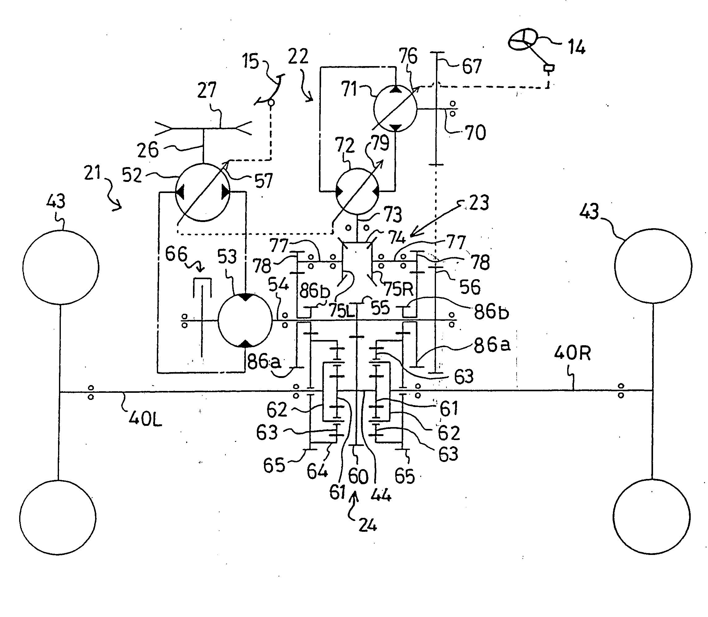
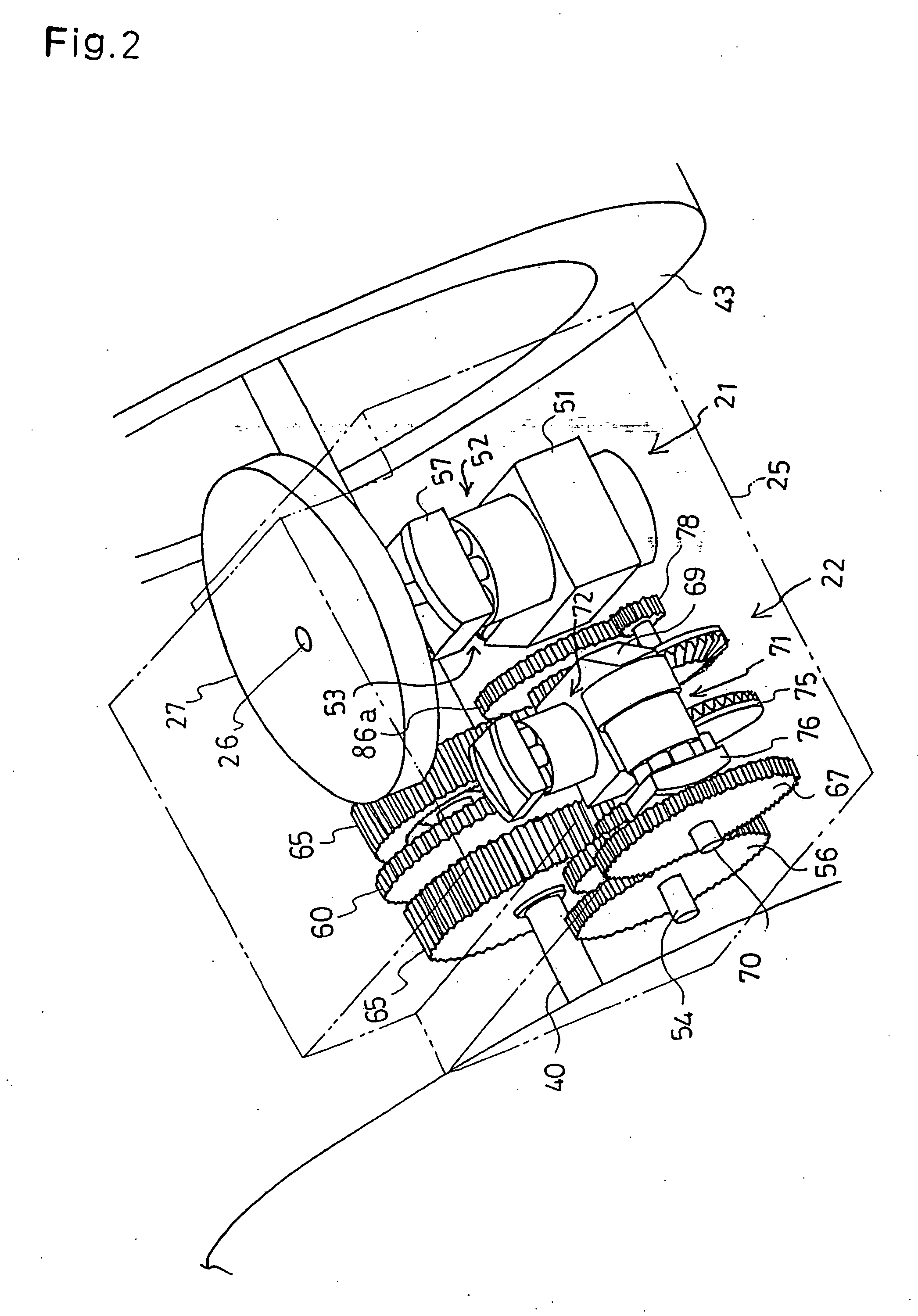
[0058] Next, referring to FIGS. 2,3 and 4, the internal mechanism of housing 25 as transmission 2 comprising HSTs 21 and 22 and differentials 24 and 23 will be described in accordance with the present invention.

[0059] First HST 21 for speed change in traveling is a well-known combination of a variable capacity type hydraulic pump 52 and a fixed capacity type hydraulic motor 53. A pump shaft of hydraulic pump 52 constitutes input shaft 26 vertically supported in housing 25. Hydraulic pump 52 is fitted onto a horizontal portion of a center section 51 fixed to the interior of housing 25. Hydraulic motor 53 is fitted to a vertical portion of center section 51 behind the horizontal portion thereof. A motor shaft 54 of hydraulic motor 53 is laterally axially disposed. Hydraulic pump 52 and hydraulic motor 53 are fluidly connected with each other through a closed circuit in center section 51.

[0060] Hydraulic pump 52 is provided with a movable swash plate 57 as an output speed changing mea...

second embodiment

[0088] A second embodiment for obtaining the similar relation between the traveling speed and the steering angle is shown in FIGS. 12 and 13. In this embodiment, hydraulic motor 72 for steering is a fixed capacity type, and two links are interposed between steering wheel 14 and swash plate 76 of hydraulic pump 71, wherein a ratio of one link to the other is changeable in length corresponding to the depth of trod pedal 15.

[0089] The base of stem 14a integral with steering wheel 14 interlocks with a Pitman 130. An utmost end of Pitman 130 is pivotally connected with a rotary link 132 through a connecting rod 131. Link 132 is pivoted at its intermediate portion around a pivotal shaft 133. The portion of link 132 opposite to the utmost end of Pitman 130 with respect to shaft 133 is bored by a longitudinally long hole 132a. A pivotal pin 134 slidably passes through hole 132a.

[0090] Pin 134 also slidably passes through a long hole 135a longitudinally bored in a portion of a control link ...

sixth embodiment

[0109] In a sixth embodiment shown in FIG. 18, center sections 51 and 69 face each other. Motor shaft 54, which is in common with the input shaft of hydraulic pump 71 of second HST 22, passes through center section 51. Traveling drive gear 55 fixed on shaft 54 directly engages with differential ring gear 92 of first differential 24′. Small diametric speed reduction gear 105 fixed on the outside portion of each first differential output shaft 40 engages with large diametric speed reduction gear 106 fixed on each axle 107.

[0110] Motor shaft 73 of second HST 22 passes through center section 69 so as to project into the space between center sections 51 and 69. Plain gear 93 fixed on shaft 73 directly engages with differential ring gear 95 of second differential 23′. One of gears 97 fixed on second differential, output shafts 96, directly engages with gear 106 on one of axles 107 and the other gear 97 engages with gear 106 on the other axle 107 through a reversing gear 98.

[0111] Transmi...


PUM


Abstract

A transmission for speed changing and steering of a vehicle comprises a first HST and a first differential for speed changing and a second HST and a second differential for steering. The first HST is a combination of a hydraulic pump and motor. The pump is driven by an engine and the motor is drivingly changeable by operation of a speed change pedal. Output power from the motor is transmitted into a pair of first differential output shafts as axles through the first differential. The second HST is a combination of a hydraulic pump and motor. The second pump is driven by output power from the first HST and the second motor is drivingly changeable by operation of a steering wheel. A pair of second differential output shafts are rotated in opposite directions by output power of the motor, so that when turning, the first differential output shaft on the opposite side of the turning direction is accelerated.

Description

BACKGROUND OF THE INVENTION [0001] 1. Field of the Invention [0002] The present invention relates to a transmission for driving left and right axles of a vehicle comprising a pair of hydrostatic transmissions (to be referred to as HSTs), each of which is a fluid combination of a hydraulic pump and a hydraulic motor, wherein one of the HSTs is provided for speed change in advancing and reversing and the other is for steering. [0003] 2. Related Art [0004] U.S. Pat. No. 4,782,650, for example, describes a vehicle provided with a pair of HSTs disposed in a lateral row and connected with each other, with left and right axles projecting laterally outward from its respective HST. Driving wheels are fixed onto utmost ends of the axles. The left and right axles are driven by changing the angles of slant of movable swash plates provided for the its respective left or right HST. [0005] The left and right axles are driven at the same speed by the pair of HSTs when the vehicle is advancing or re...

Claims


Application Information

Patent Timeline
Patent Type & Authority Applications(United States)
IPC IPC(8): B62D11/18F16H47/04
CPCB60K17/105B60Y2200/223B62D11/006F16H2047/045B62D11/183F16H47/04B62D11/18
Inventor HASEGAWA, TOSHIYUKIMCCLOUD, TRAVIS S.ANDREWS, KEITH J.ABEND, ROBERT
Owner HASEGAWA TOSHIYUKI
Why Eureka
Try Eureka