Brake pedal apparatus

a pedal apparatus and pedal technology, applied in the direction of mechanical control devices, apparatus for force/torque/work measurement, instruments, etc., can solve the problems of inability to obtain a braking force, limitation in the amount of possible displacement of the connected position, and difficulty in largely so as to reduce the cost, reduce the effect of braking operation and greatly changing the lever ratio characteristi

Inactive Publication Date: 2006-10-19
TOYODA IRON WORKS CO LTD
View PDF18 Cites 18 Cited by
  • Summary
  • Abstract
  • Description
  • Claims
  • Application Information

AI Technical Summary

Benefits of technology

[0015] In the brake pedal apparatus constructed as described above in which one of the connected positions of the connecting link is adapted to changeable, the one of the connected positions is shifted when the depression force exceeds the predetermined value, whereby the lever ratio characteristic is changed. This arrangement makes it possible to provide a further satisfactory braking operation feeling corresponding to a depression force. Further, this arrangement permits the connected position to be shifted with a higher degree of freedom than in an arrangement in which the connected position of the output member is shifted, because of absence of limitation arising from change of posture of the output member. The higher degree of freedom as to shift of the connected position enables the lever ratio characteristic to be greatly changed in accordance with a braking command (depression force) given by a vehicle driver.
[0016] In the third invention, the lever-ratio characteristic changing device is constructed to be equipped with the control lever and the pivoting device, wherein the control lever can be held in the reference position by a relatively small force of the pivoting device corresponding to the lever ratio of the control lever (a ratio between a length of moment arm of force acting on the connected position and a length of moment arm of force acting on the engaging portion). This arrangement permits the lever-ratio characteristic changing device including the pivoting device, to be made compact in size at a reduced cost.
[0017] In the fourth invention, the electric driving device is used in the pivoting device, so that the control lever is arranged to be electrically pivotable. This arrangement facilitates determination of a value (predetermined value) of the depression force at which the lever ratio characteristic is to changed, thereby permitting the value to be freely determined in relation to, for example, type of vehicle. Further, in this arrangement, the lever ratio characteristic may be changed in a single step when the depression force reaches the predetermined value, or alternatively may be changed gradually or in a plurality of steps in accordance with the depression force. That is, it is possible to freely determine a changing manner according to which the lever ratio characteristic is to be changed. Further, it is also possible to select, in relation to a vehicle condition, a suitable mode according to which the predetermined value and the changing mode are to be changed.
[0018] In the fifth invention, the pivoting device is constituted by an elastic member, such that the control lever is held by the biasing force of the elastic member, in the reference position, and such that the control lever is mechanically allowed to be pivoted away from the reference position against the biasing force of the elastic member when the depression force exceeds the predetermined value. In this arrangement, the lever ratio characteristic is gradually changed owing to continuous change of the biasing force as a result of an elastic deformation of the elastic member. Further, the apparatus can be constructed easier and cheaper, eliminating necessity of a complicated control, as compared with an arrangement in which the control lever is arranged to be pivoted by using the electric driving device.

Problems solved by technology

Therefore, when the brake pedal apparatus is operated with application of a large depression force thereto for quickly obtaining a large braking force, for example, it is not necessarily possible to obtain a braking force and a braking operation feeling corresponding to a braking command given by a vehicle driver.
In Patent Document 2, however, the change of the connected position, at which the output member is connected to the operating pedal, results in a change of posture (angle) of the output member, thereby providing a limitation in amount of possible displacement of the connected position and consequently making it difficult to largely change the lever ratio characteristic.
Further, in Patent Document 2, the connected position is directly biased by a spring, which is required to generate a large spring force and accordingly has to be large in size and high in cost.

Method used


Image

  • Brake pedal apparatus
  • Brake pedal apparatus
  • Brake pedal apparatus

Examples


Embodiment Construction

[0036] There will be described in detail embodiments of the present invention, with reference to the drawings.

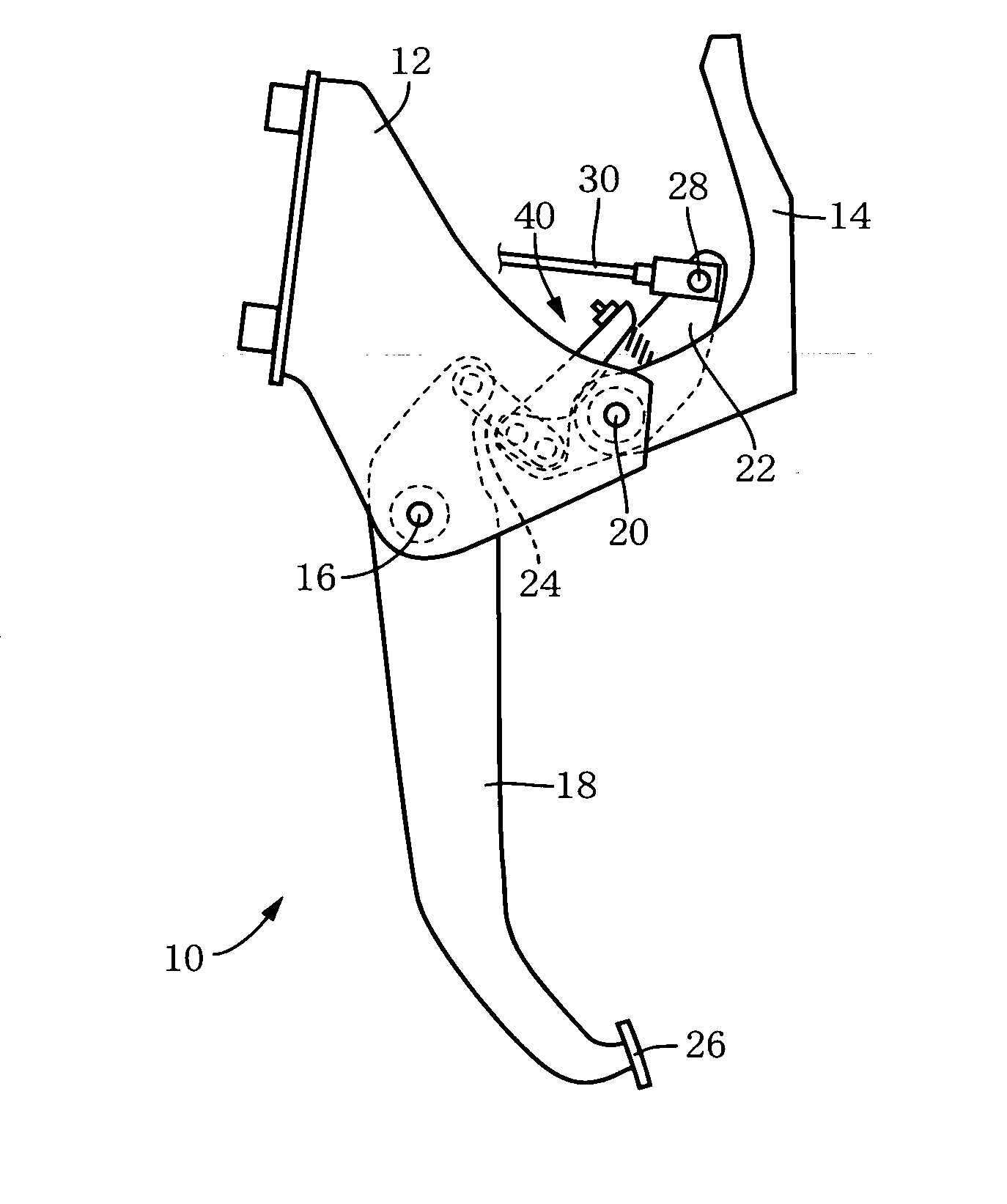
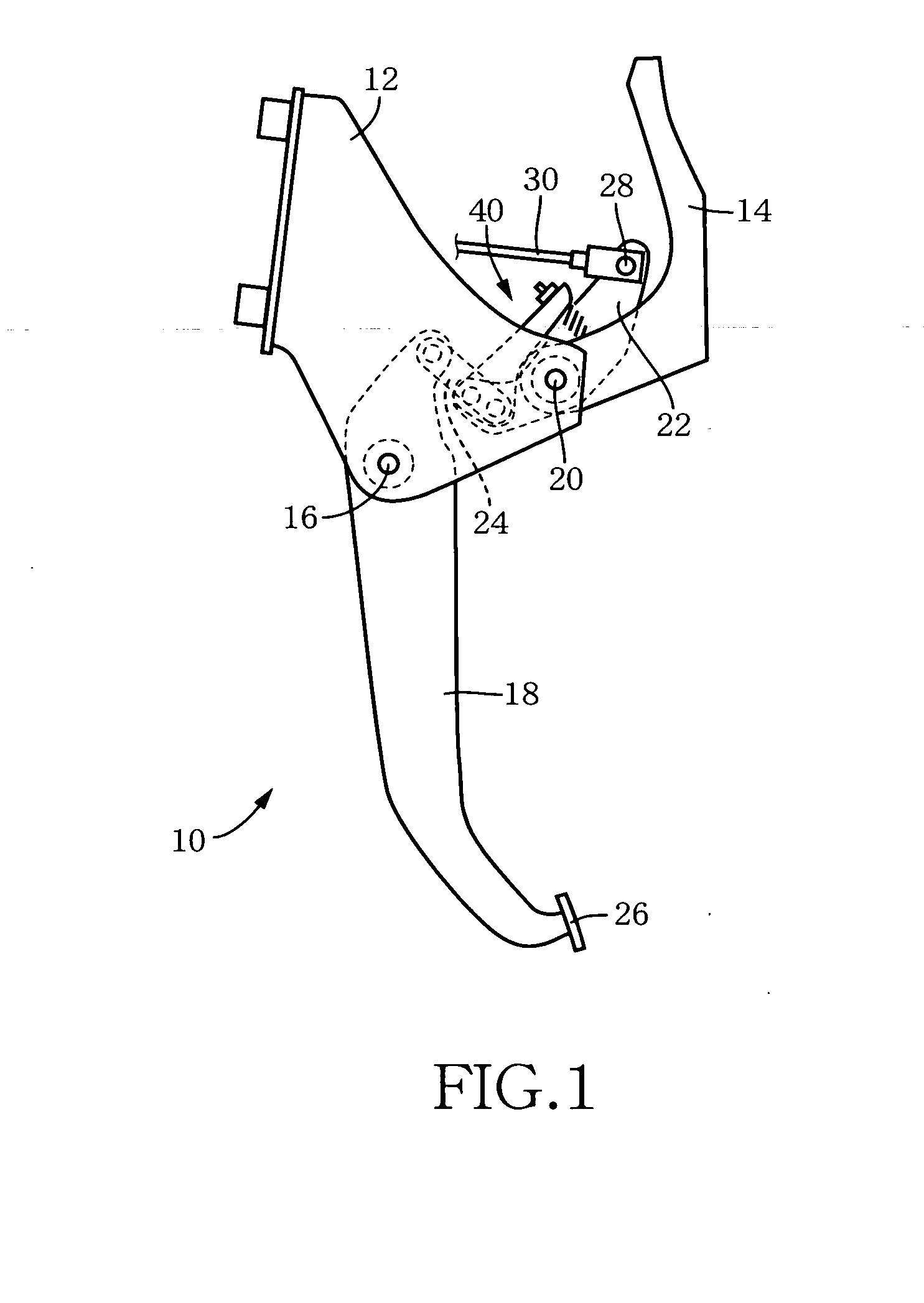
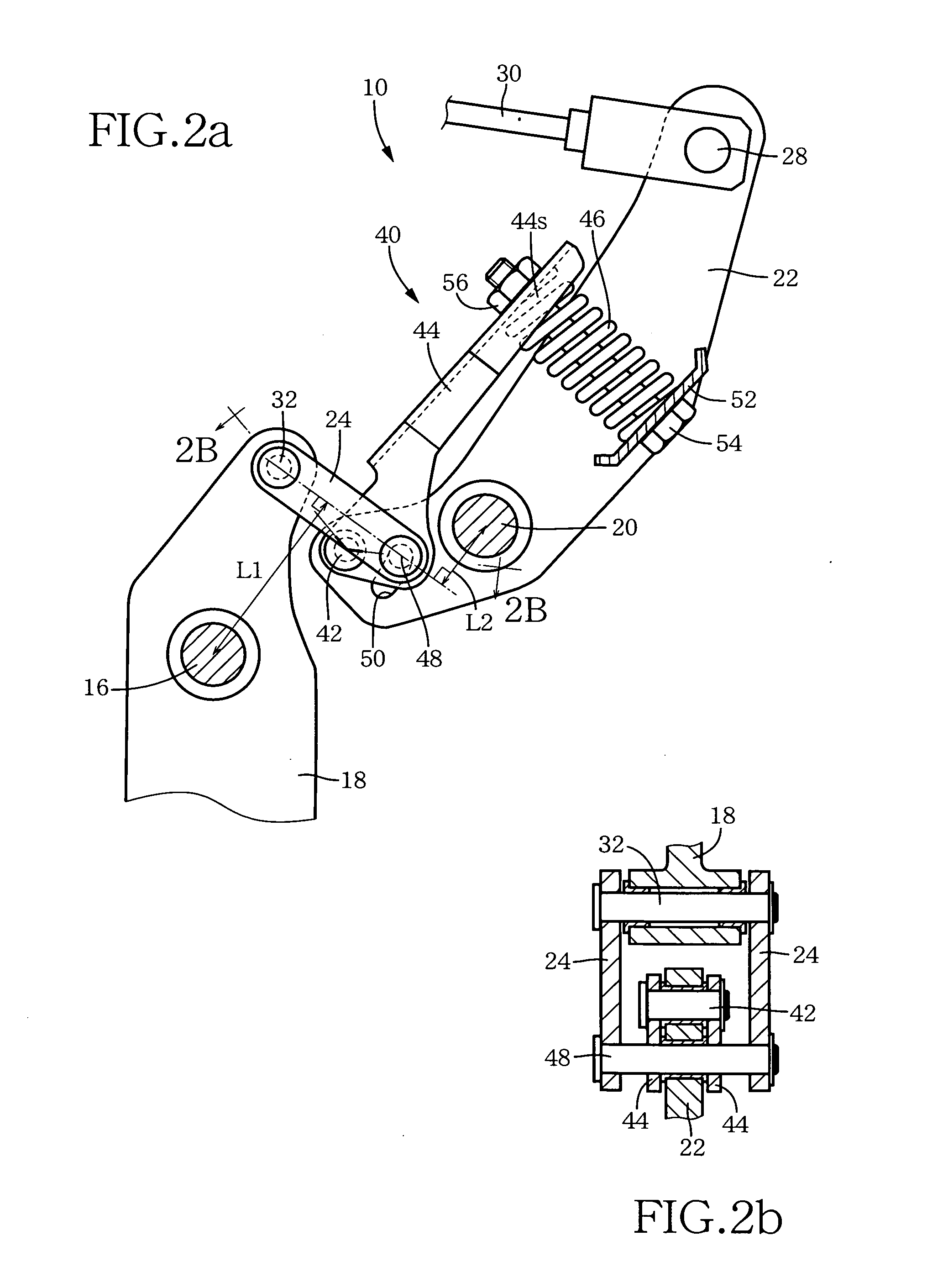
[0037]FIG. 1 is a front view schematically showing an embodiment of the invention in the form of a brake pedal apparatus 10 which is to be used for a service braking system of a vehicle. This brake pedal apparatus 10 is provided in brackets 12, 14 which are integrally fixed to a body of the vehicle. An operating pedal 18 is provided in the bracket 12, so as to be pivotable about an axis of a first support shaft 16 which is substantially horizontal. The brackets 12, 14 are connected through a second support shaft 20 on which a pivot member 22 is mounted to be pivotable about an axis of the second support shaft 20. A connecting link 24 is provided to extend between the operating pedal 18 and the pivot member 22. The first and second support shafts 16, 20 are held in parallel to each other, and the axes of the first and second support shafts 16, 20 correspond to a first axis a...


PUM


Abstract

A brake pedal apparatus includes: an operating pedal to be depressed so as to be pivoted about a first axis; a pivot member pivotable about a second axis parallel to the first axis, and connected to the operating pedal via a connecting link so as to be pivoted about the second axis in response to a depression of the operating pedal; and an output member to receive an output generated upon pivot motion of the pivot member. The connecting link is connected, at respective connected positions, to the operating pedal and the pivot member. A relationship between a ratio of the output to a depression force acting on the operating pedal, and an amount of the depression of the operating pedal is changed depending upon the connected positions of the connecting link. The brake pedal apparatus further includes a ratio characteristic changing device operable, when the depression force exceeds a predetermined value, to shift at least one of the connected positions of the connecting link, for changing the relationship between the ratio and the amount of the depression of the operating pedal.

Description

BACKGROUND OF THE INVENTION [0001] 1. Field of the Invention [0002] The present invention relates in general to a brake pedal apparatus, and more particularly to an improvement of a brake pedal apparatus in which a characteristic of a lever ratio is changed depending upon a depression force. [0003] 2. Discussion of Prior Art [0004] There is known a brake pedal apparatus having (a) an operating pedal which is disposed pivotably about a first axis, (b) a pivot member which is disposed pivotably about a second axis parallel to the first axis, and which is connected to the operating pedal via a connecting link so as to be mechanically pivoted about the second axis in response to a depressing operation effected on the operating pedal; and (c) an output member which is to be mechanically pressed or pulled as a result of pivot motion of the pivot member. As an example of such a brake pedal apparatus, Patent Document 1 discloses an apparatus in which a lever ratio representative of a ratio ...

Claims


Application Information

Patent Timeline
Patent Type & Authority Applications(United States)
IPC IPC(8): G05G1/14B60T7/06
CPCB60T7/06G01L5/225Y10T74/2057Y10T74/20558Y10T74/20528
Inventor FUKASE, AKIHIKO
Owner TOYODA IRON WORKS CO LTD
Why Eureka
Try Eureka