Method to predict phase current

Active Publication Date: 2010-06-17
SAMSUNG ELECTRONICS CO LTD
View PDF9 Cites 32 Cited by
  • Summary
  • Abstract
  • Description
  • Claims
  • Application Information

AI Technical Summary

Benefits of technology

[0013]Therefore, it is an aspect of the present invention to provide a phase current prediction method to predict current representative of a PWM period using DC link

Problems solved by technology

However, in the SVPWM scheme using the single current sensor, current is measured in a switching period, not at the middle of a sampling period, resulting in occurrence of a current error.
These curren

Method used


Image

  • Method to predict phase current
  • Method to predict phase current
  • Method to predict phase current

Examples


Embodiment Construction

[0031]Reference will now be made in detail to the embodiments, examples of which are illustrated in the accompanying drawings, wherein like reference numerals refer to the like elements throughout. The embodiments are described below to explain the present invention by referring to the figures.

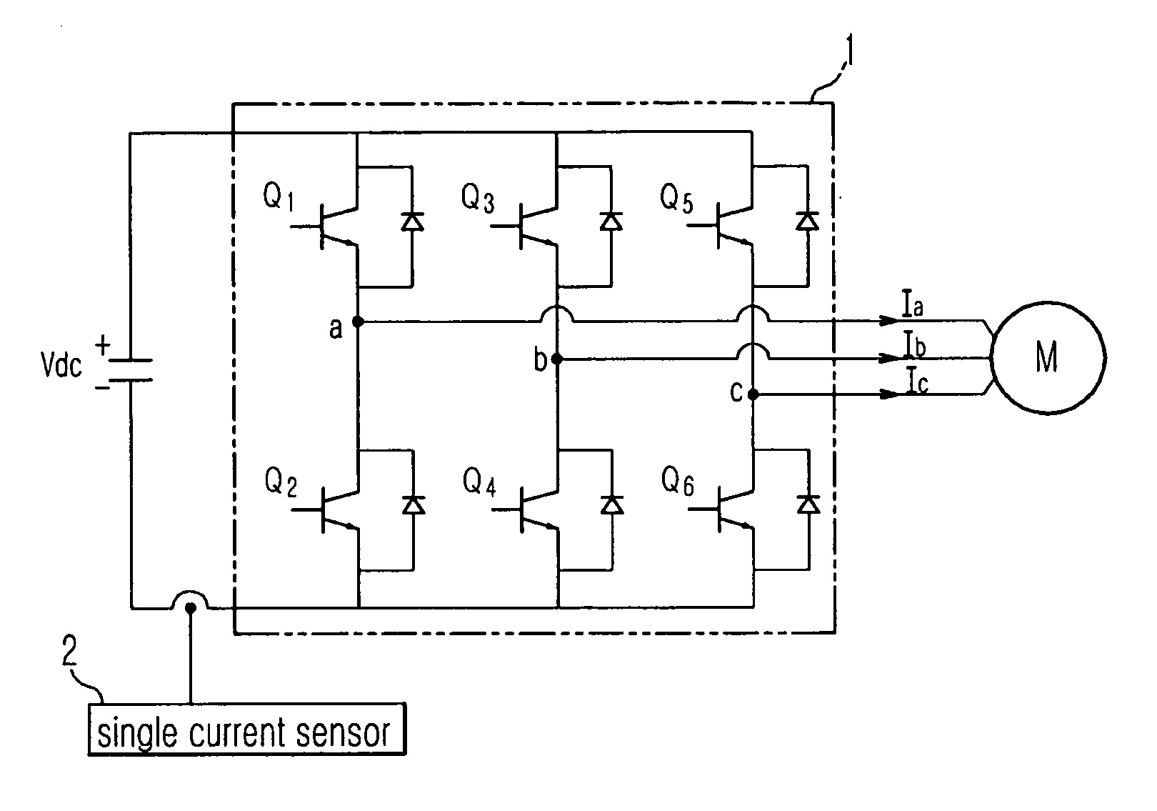
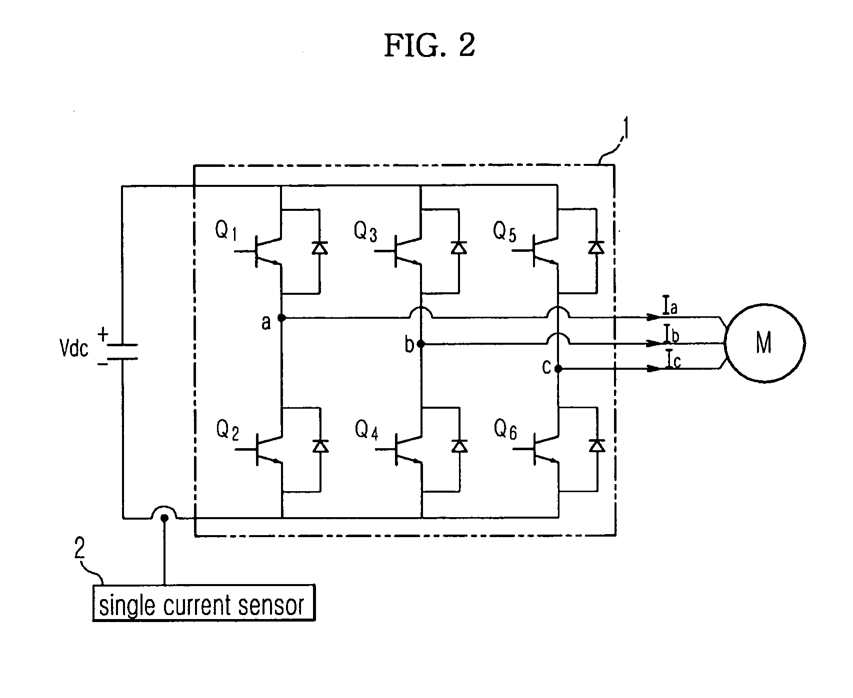
[0032]FIG. 2 shows the configuration of a 3-phase PWM inverter system using a single current sensor, to which an embodiment of the present invention is applied.

[0033]As shown in FIG. 2, a 3-phase motor M, which is an AC motor, includes a stator including resistors and inductors, and an internal rotor. The 3-phase motor M has phase terminals connected to an inverter 1. When phase currents flow to the inductors respectively through the phase terminals, a magnetic field is formed, so as to rotate the internal rotor.

[0034]The inverter 1 functions to convert a DC voltage into a pulse-shaped 3-phase AC voltage having a variable frequency through pulse width modulation (PWM) to drive the motor. To th...


PUM


Abstract

A phase current prediction method is disclosed. The phase current prediction method predicts current representative of a PWM period using a motor model which receives current measured through a single current sensor as an input, instead of the measured current, and determines the predicted current to be phase current.

Description

CROSS-REFERENCE TO RELATED APPLICATION[0001]This application claims the benefit of Korean Patent Application No. 2008-0097420, filed on Oct. 2, 2008 in the Korean Intellectual Property Office, the disclosure of which is incorporated herein by reference.BACKGROUND[0002]1. Field[0003]Embodiments of the present invention relate to a phase current prediction method to measure DC link current of an inverter through a single current sensor provided between the inverter, which drives a motor, and a DC voltage source to predict phase current of the motor.[0004]2. Description of the Related Art[0005]Generally, an inverter circuit is a power conversion device that converts direct current (DC) power into pulse-shaped 3-phase (U, V and W) alternating current (AC) power having a variable frequency. Due to reduction in energy consumption and easiness of output control, the inverter circuit has been increasingly used to drive motors used in electric products such as a washing machine, refrigerator...

Claims


Application Information

Patent Timeline
IPC IPC(8): G01R19/00G06F19/00
CPCH02M2001/0009H02M7/53875H02M1/0009G01R19/14G01R19/15G01R21/06
Inventor HA, JUNG IKKIM, JONG HOYOO, HO SUNYOU, HYUNG SUNKIM, JANG HWAN
Owner SAMSUNG ELECTRONICS CO LTD
Why Eureka
Try Eureka