Clamp meter with safe trigger mechanism

Inactive Publication Date: 2010-06-17
RISHABH INSTR PVT +1
View PDF2 Cites 19 Cited by
  • Summary
  • Abstract
  • Description
  • Claims
  • Application Information

AI Technical Summary

Benefits of technology

[0012]One advantage of the present invention is that the clamp jaws can be opened or closed with the trigger placed at the bottom side which is a safe location as it allows the operator to place his hand as far away from the live conductor as possible, The danger of exposing human beings to electric shocks is minimized due to such innovative design.

Problems solved by technology

The opening of clamp jaws may require substantial force.
This can cause fatigue to the hand of the operator as all the force required to open the clamp jaws for enclosing the conductor is sustained by the thumb.
A drawback of the existing clamp meters is they are awkward to use in many circumstances.
For example, there are many situations where the conductor elements that need monitoring are tightly and awkwardly placed in congested physical configurations, or placed in an overhead location, thereby making it awkward to work with them.
Under these circumstances, when the clamp jaws are placed around conductor, the display and the keys might be orientated into a position which makes reading the display and operation of the clamp meter very difficult if not impossible.
The operator of the clamp meter tries, under such circumstances, either to take a reading by putting at risk their personal safety or they may not take any measurements at all on the grounds of lack of safe access to the conductor element.
As a further drawback of the existing clamp meters, as the thumb-operated lever is very close to the clamps, user is exposed to dangerously high voltage when measuring the current in the live and often bare conductor elements.
When accessing conductors situated in congested or awkward locations, there is also a possibility that the clamp may slip accidentally and user may touch the live conductor and get electrocuted and thus could suffer serious injuries or fatality.
This poses a definite risk to the property which houses the electric panels that contain such electric conductor elements.

Method used


Image

  • Clamp meter with safe trigger mechanism
  • Clamp meter with safe trigger mechanism
  • Clamp meter with safe trigger mechanism

Examples


Embodiment Construction

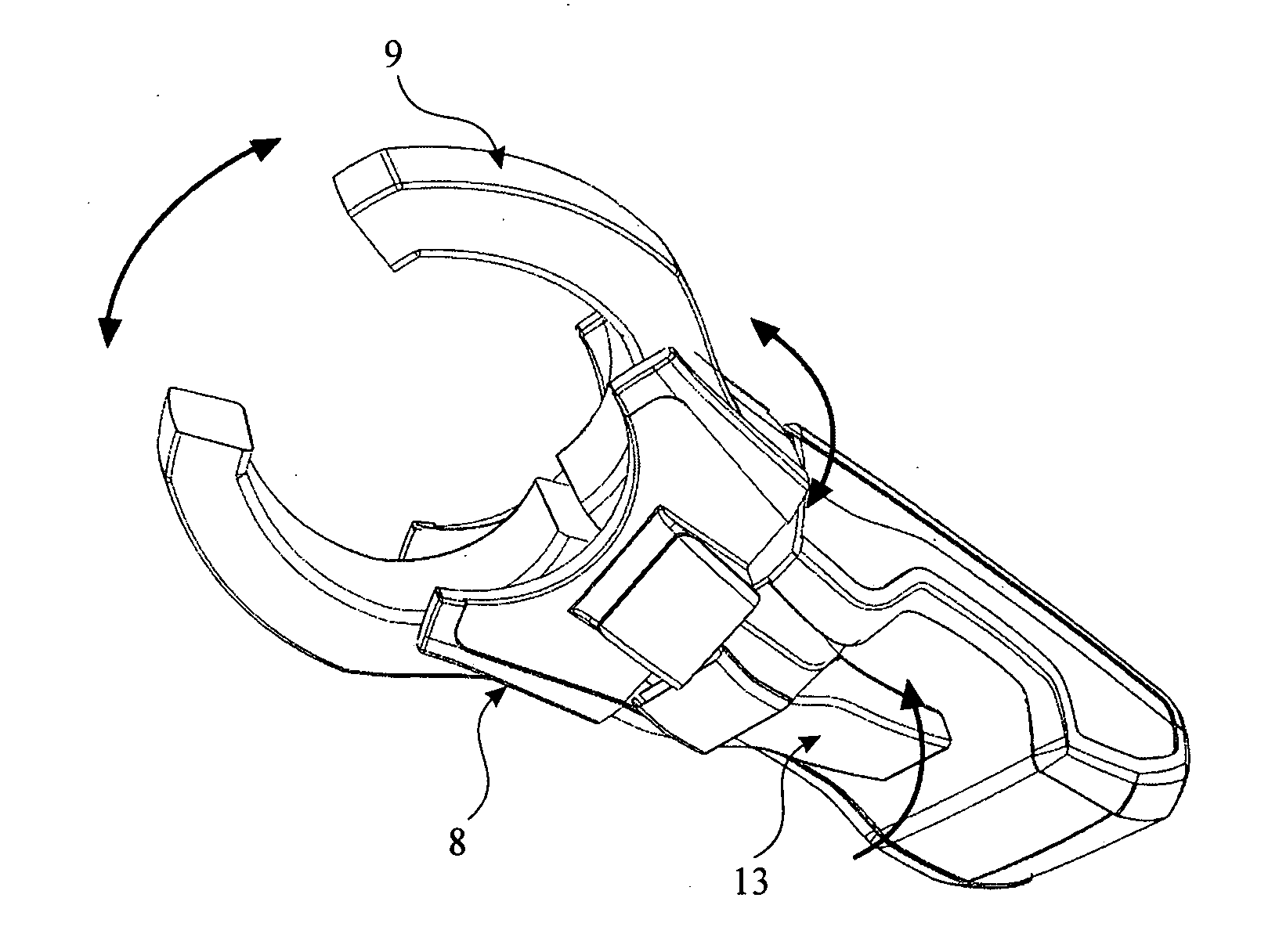
[0024]The present invention provides a clamp meter that has a safe trigger (13) for operating the clamps of a clamp meter. The trigger mechanism may be used in the current non-rotary type clamp meters, where the clamp jaws (9) do not rotate out of their own plane. The trigger mechanism of the present invention may also be used in the rotary type clamp meters where the clamp jaws (9) are able to rotate out of their own plane.

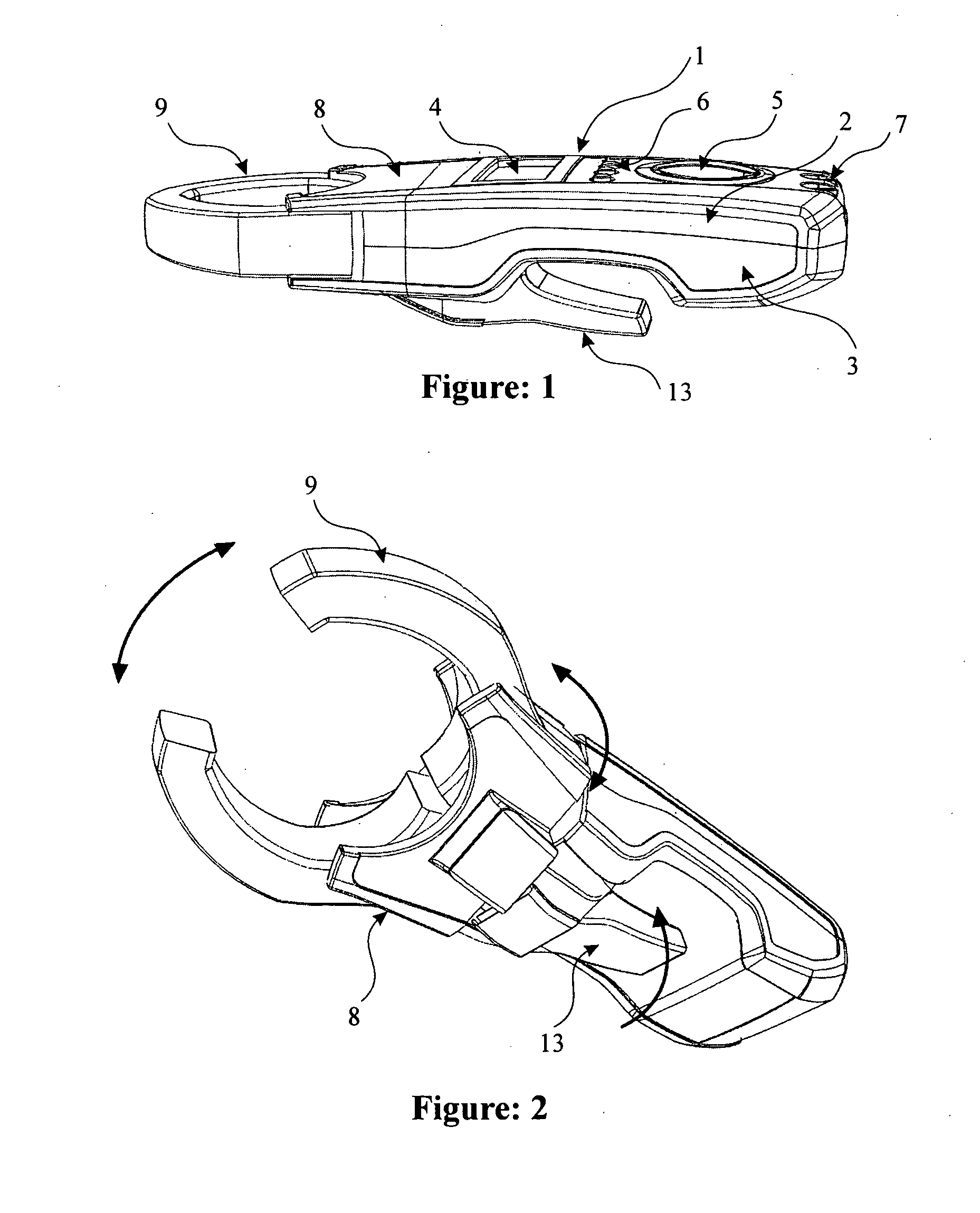
[0025]Referring to FIG. 1, the main body (1) of the clamp meter of the present invention is made of cover housing (2) and a base housing (3), the two housings enclosing the measurement circuitry and some of the other parts of the clamp meter. A display screen (4), a function selection switch (5), and a set of push buttons (6) to select testing parameters are housed within the housings and electrically connected to the measurement circuitry. Two input terminals (7) are also provided for connecting the test leads.

[0026]FIG. 2 shows the underside of the clamp meter ...


PUM


Abstract

This invention provides a clamp meter with safe trigger mechanism which allows an operator to take electrical measurements of the conductors safely, particularly in case of the electrical conductor elements situated in congested or awkward locations and positions. In the preferred embodiment of the present invention, the trigger is placed at the underside of said clamp meter so as to allow convenient access to it for the fingers of a hand while the clamp meter is held in the hand. The trigger mechanism of the invention may be operated with single or multiple fingers. The invention also allows the hand to maintain its ‘clinched-fist’ position throughout the measurement process, thereby eliminating the need to open the hand any time during the process. The invention thus makes the electrical parameter measurement operation using clamp meters safer than for the conventional meters.

Description

CROSS REFERENCE TO RELATED APPLICATIONS [0001]This application is a 371 National Stage entry of PCT / IN2008 / 000296, filed on May 13, 2008, which claims priority to Indian Patent Application Number 931 / MUM / 2007, filed on May 18, 2007.FIELD OF THE INVENTION [0002]This invention relates generally to electrical and electronic test and measuring instruments for measuring electrical current and particularly relates to multi meters that include clamp meters for the electrical current measurement.BACKGROUND OF THE INVENTION[0003]Multimeters are used to measure a variety of electrical parameters such as AC voltage, AC current, DC voltage, DC current, and resistance. Clamp meters are a type of multimeters with a current sensing clamp.[0004]Clamp meters are designed to measure current without breaking the current path and typically have two clamp jaws which open and close at a fixed position with respect to the body and display of the clamp meter. Current is measured by opening the jaws to clos...

Claims


Application Information

Patent Timeline
IPC IPC(8): G01R1/20
CPCG01R1/22
Inventor SHAH, TUSHAR GAJKUMARSHAHANE, KULDEEP HIMMATRAODESHMUKH, AMOL ASHOKRAO
Owner RISHABH INSTR PVT
Why Eureka
Try Eureka