
Compact adaptive optic- optical coherence tomography system

a tomography system and adaptive optic technology, applied in the field of adaptive optics in optical coherence tomography, can solve the problems of limited real-time ocular-aberration compensation and small amount in previous ao-oct instruments, and achieve the effects of reducing ao registration errors, reducing pupil shift at the mems, and improving ao performan

Inactive Publication Date: 2010-06-17
LAWRENCE LIVERMORE NAT SECURITY LLC
View PDF5 Cites 29 Cited by
  • Summary
  • Abstract
  • Description
  • Claims
  • Application Information

AI Technical Summary

Benefits of technology

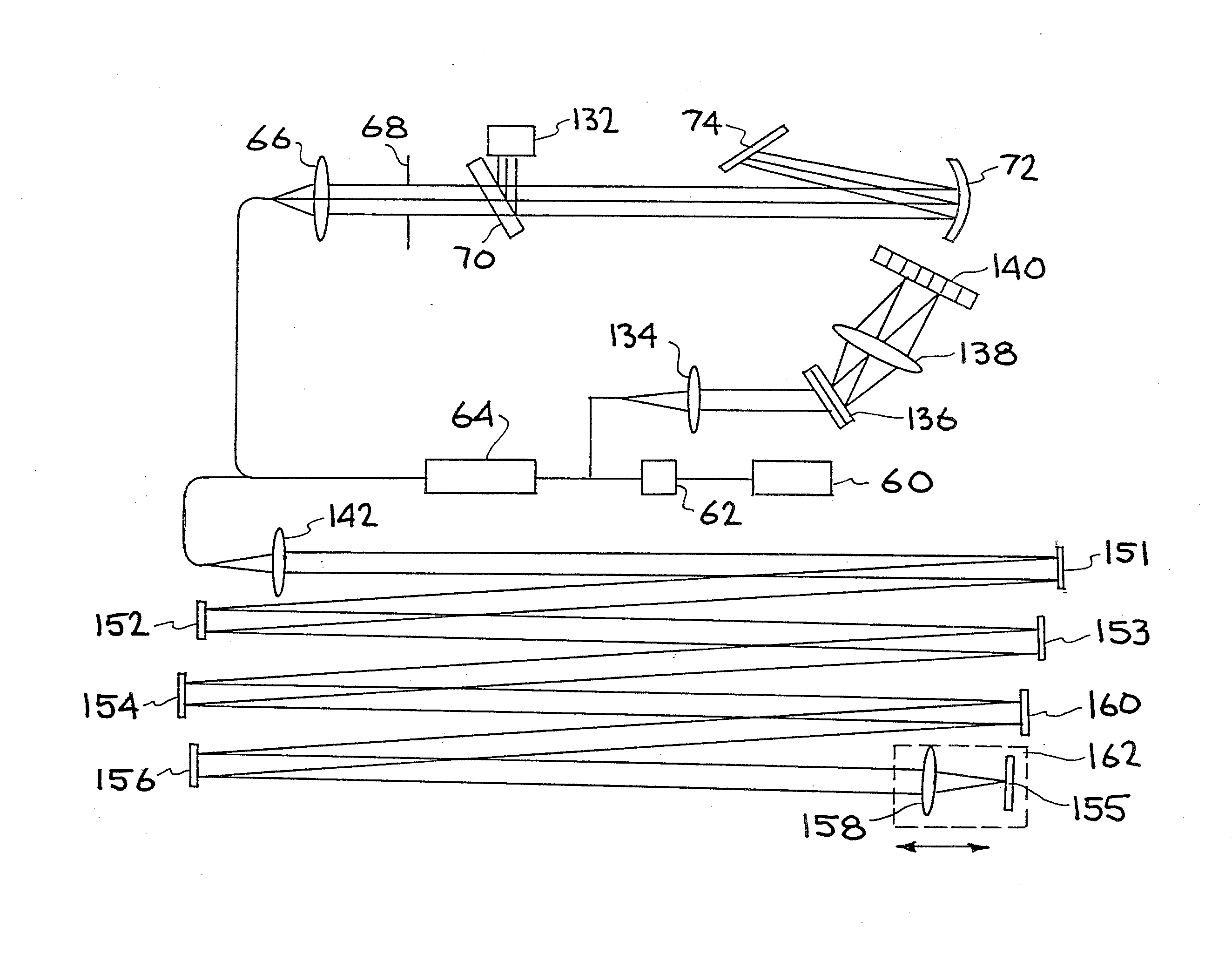
[0010]It is an object of the present invention to provide a compact AO-OCT system that includes a Badal optometer and rotating cylindrical lenses to compensate for defocus and astigmatism, respectively, and a micro-electro-mechanical system (MEMS)-based adaptive optic to compensate for high-order aberrations.
[0012]Embodiments of the present invention include an optical apparatus to correct the spectacle aberrations of patients. Such aberrations include myopia, hyperopia and astigmatism. Residual aberrations are compensated by a MEMS DM, which is placed between the light source, e.g., a superluminescent diode (SLD) light source, and the XY scanners in the AO-OCT system, to minimize the pupil shift at the MEMS. In addition, the compact AO-OCT system is optimized to have minimum system aberrations to reduce AO registration errors and improve AO performance. Unlike the previous large systems which were set-up on a standard lab table, embodiments of the present AO-OCT system are specifically designed for clinical use requiring compact size, low cost, and high reliability.
[0013]Accordingly, embodiments of compact MEMS-based adaptive optic (AO) optical coherence tomography (OCT) systems with improved AO performance and ease of clinical use are described. Adaptive optic systems often consist of a Shack-Hartmann wavefront sensor and a deformable mirror that measures and corrects ocular and system aberrations. Because of limitations on current deformable mirror technologies, the amount of real-time ocular-aberration compensation is restricted and small in previous AO-OCT instruments. The present invention eliminates the tedious process of using trial lenses in clinical imaging. Different amounts of spectacle aberration compensation are achieved, e.g., by motorized stages, and automated with the AO computer for ease of clinical use. In addition, embodiments of the present invention include a compact AO-OCT system that is optimized to have minimum system aberrations to reduce AO registration errors and improve AO performance.

Problems solved by technology

Because of limitations on current deformable mirror technologies, the amount of real-time ocular-aberration compensation is restricted and small in previous AO-OCT instruments.

Method used


Image

  • Compact adaptive optic- optical coherence tomography system
  • Compact adaptive optic- optical coherence tomography system
  • Compact adaptive optic- optical coherence tomography system

Examples


Embodiment Construction

[0026]Embodiments of the present invention include an AO-OCT system consisting of three channels: (1) a sample (or signal) channel, equipped with an AO for collecting the retinal image, (2) a reference channel with an optical path length matching that of the sample channel, and (3) detection channel for recording the combined sample and reference signals. The sample channel length is from the beamsplitter (BS) (e.g., from an 80 / 20 BS) to the target and back to the splitting point of the BS. The reference channel length is from the BS to a mirror at the end of the channel and back.

TABLE 1Summary of exemplary system componentsLight sourceSuperluminescent diode (SLD) from Superlumλ = 842 nm, δλ = 50 nmDeformable mirrorMEMS from Boston Michomachines Corp.3.3 mm × 3.3 mm optical aperture,12 × 12 actuators1.5 μm strokeHorizontal / verticalCambridge Technology; 6220M40 galvanometricscannersscanner, ±20°Wavefront sensorShack-Hartmann wavefront sensorLens array from Adaptive Optics Associates2...


PUM


Abstract

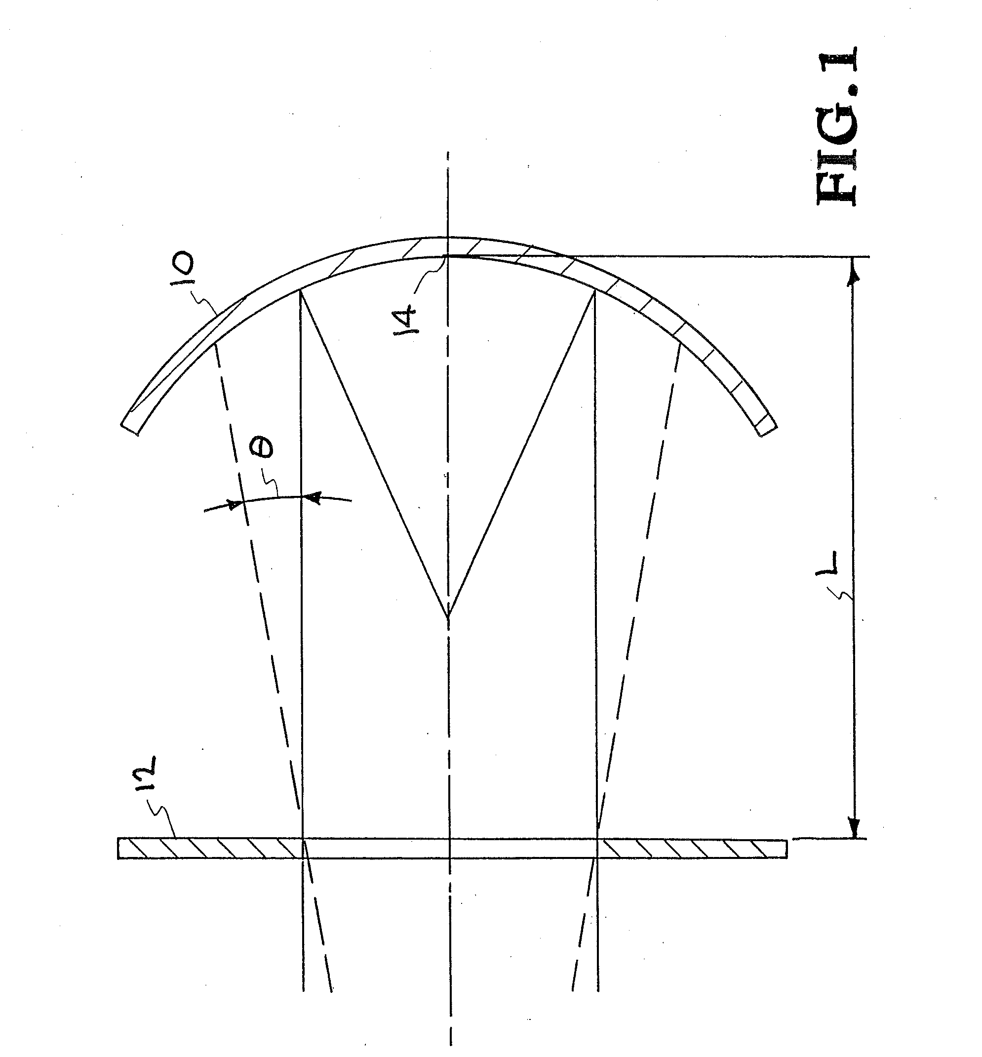
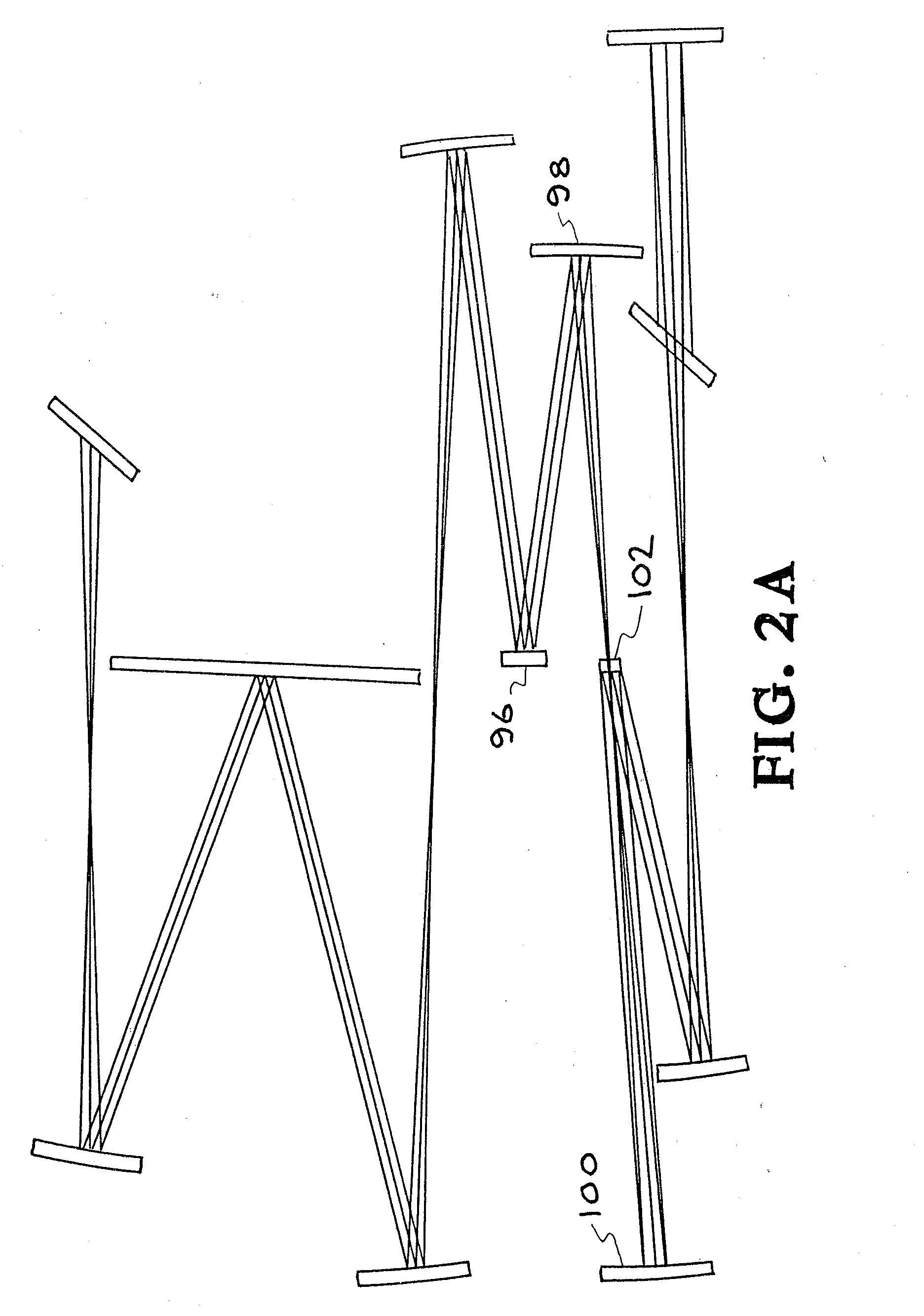
Badal Optometer and rotating cylinders are inserted in the AO-OCT to correct large spectacle aberrations such as myopia, hyperopic and astigmatism for ease of clinical use and reduction. Spherical mirrors in the sets of the telescope are rotated orthogonally to reduce aberrations and beam displacement caused by the scanners. This produces greatly reduced AO registration errors and improved AO performance to enable high order aberration correction in a patient eyes.

Description

[0001]This application claims priority to U.S. Provisional Patent Application Ser. No. 61 / 146,575, filed Jan. 22, 2009, titled: “Compact Adaptive Optic-Optical Coherence Tomography System” incorporated herein by reference. This application is a continuation-in-part of U.S. patent application Ser. No. 11 / 874,832 titled “High-resolution Adaptive Optics Scanning Laser Opthalmoscope with Multiple Deformable Mirrors,” filed Oct. 18, 2007, incorporated herein by reference. U.S. patent application Ser. No. 11 / 874,832 claims priority to U.S. Provisional Patent Application Ser. No. 60 / 852,857, filed Oct. 18, 2006.[0002]The United States Government has rights in this invention pursuant to Contract No. DE-AC52-07NA27344 between the United States Department of Energy and Lawrence Livermore National Security, LLC.BACKGROUND OF THE INVENTION[0003]1. Field of the Invention[0004]The present invention relates to optical coherence tomography, and more specifically, it relates to the use of adaptive o...

Claims


Application Information

Patent Timeline
IPC IPC(8): A61B3/14A61B3/00
CPCG02B17/004G02B17/023G02B17/0647G02B26/0833A61B3/14G02B27/1086G02B27/144G02B27/40G02B27/0068G01B9/02044G01B9/02068G01B9/02091
Inventor OLIVIER, SCOT S.CHEN, DIANA C.JONES, STEVEN M.MCNARY, SEAN M.
Owner LAWRENCE LIVERMORE NAT SECURITY LLC
Learn More