System and method for a subscriber powered network element

a subscriber and network element technology, applied in the direction of transmission monitoring, multiplex communication, current supply arrangement, etc., can solve the problems of not supporting high bandwidth, too large reach and bandwidth limitations, and the added burden of maintaining the multitude of optical to copper drop sites, so as to reduce labor installation time and cost, and cost effective

Active Publication Date: 2010-06-17
SOTO ALEXANDER I +1
View PDF40 Cites 167 Cited by
  • Summary
  • Abstract
  • Description
  • Claims
  • Application Information

AI Technical Summary

Benefits of technology

[0012]According to the present invention, techniques related to local powering of a network element or drop site of a wide area access network by a subscriber terminal, adaptor, router, server, gateway, or customer premise equipment (CPE) which combines an electrical power signal or electricity, which may be derived from subscriber mains power (e.g., AC power), with the electrical data communications as a combined electrical WAN signal over the same communication medium connecting the network element or drop site and the subscriber terminal, adaptor, router, server, gateway or CPE are provided. Certain advantages and / or benefits may be achieved using embodiments of the present invention. For example, the embodiments of the present invention have the advantage of being free of any requirement for additional meter installations or meter connection charges. Additionally, embodiments of the present invention have the advantage of reducing labor installation time and costs and enabling subscriber self installation. Furthermore, embodiments of the present invention do not create a separate power network. The information network and the power network are the same network in that they share the same transmission line (e.g., twisted copper wire pair or twisted wire pair, coaxial cable or Ethernet cable), thus the communication network can be powered in a cost effective and maintainable manner.

Problems solved by technology

Twisted wire pair cable, such as used in plain old telephone services, do not support high bandwidths over a great distance; and while coaxial cables, such as used in cable television services, do a better job, it too has reach and bandwidth limitations.
One major problem with bringing fiber cable within a short distance of a subscriber location is the added burden of maintaining the multitude of optical to copper drop sites.
Optical fiber itself is not capable of carrying the electricity to power these drop sites.
This creates a challenge in planning, distributing and deployment of electricity to power the drop site energy needs.
Increased voltages raise craft safety issues.
Furthermore, there is the 24-hour a day cost of supplying electricity to the power network, as well as regular maintenance and support of the power network itself including regular replacement of batteries for Lifeline services, which are generally located at the CO or head end.
This results in a large number of battery sites and power access points.
Generally the cost of this type of system is high primarily due to the cost of connecting drop sites to a commercial power source.
This poses a major problem when the monthly energy consumption of a drop site is significantly lower than the minimum charge.
However, its use is limited to areas with direct access to sunlight as the output of solar panels decreases with a reduction in incident solar energy.
Therefore, this strategy cannot be used everywhere.

Method used


Image

  • System and method for a subscriber powered network element
  • System and method for a subscriber powered network element
  • System and method for a subscriber powered network element

Examples


Embodiment Construction

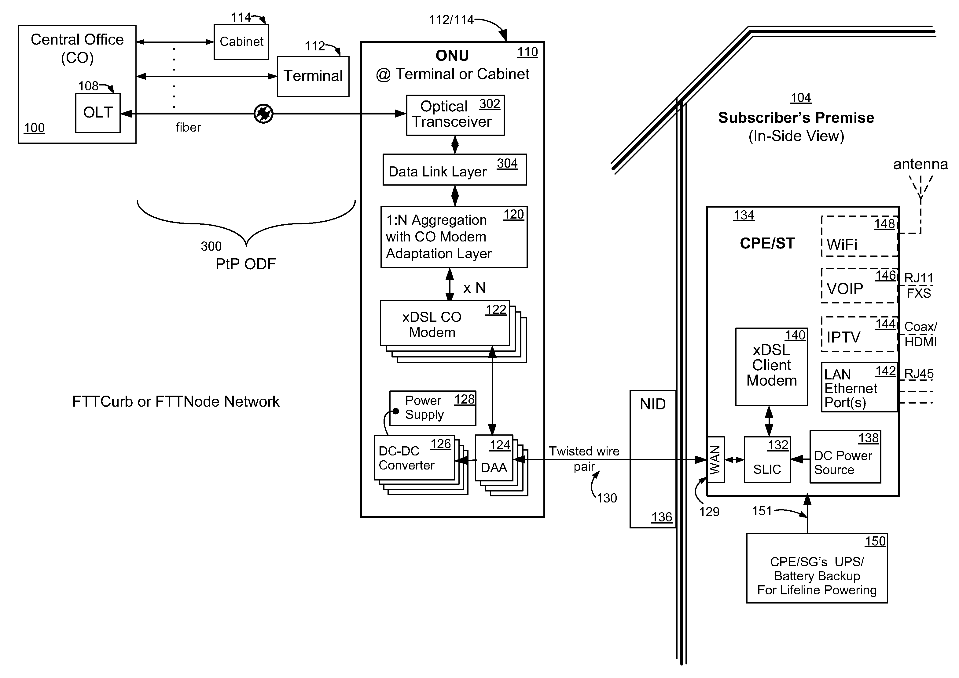
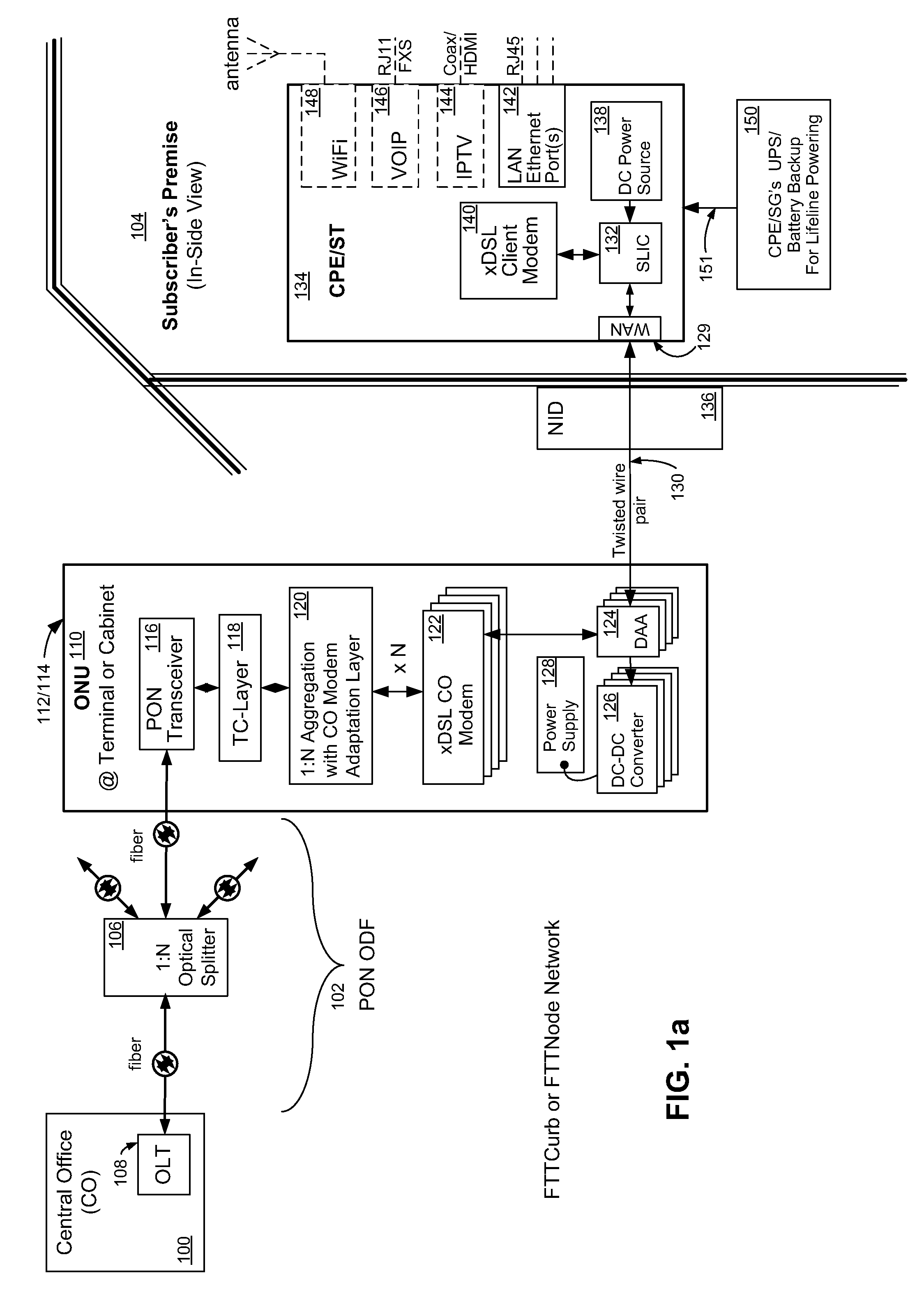
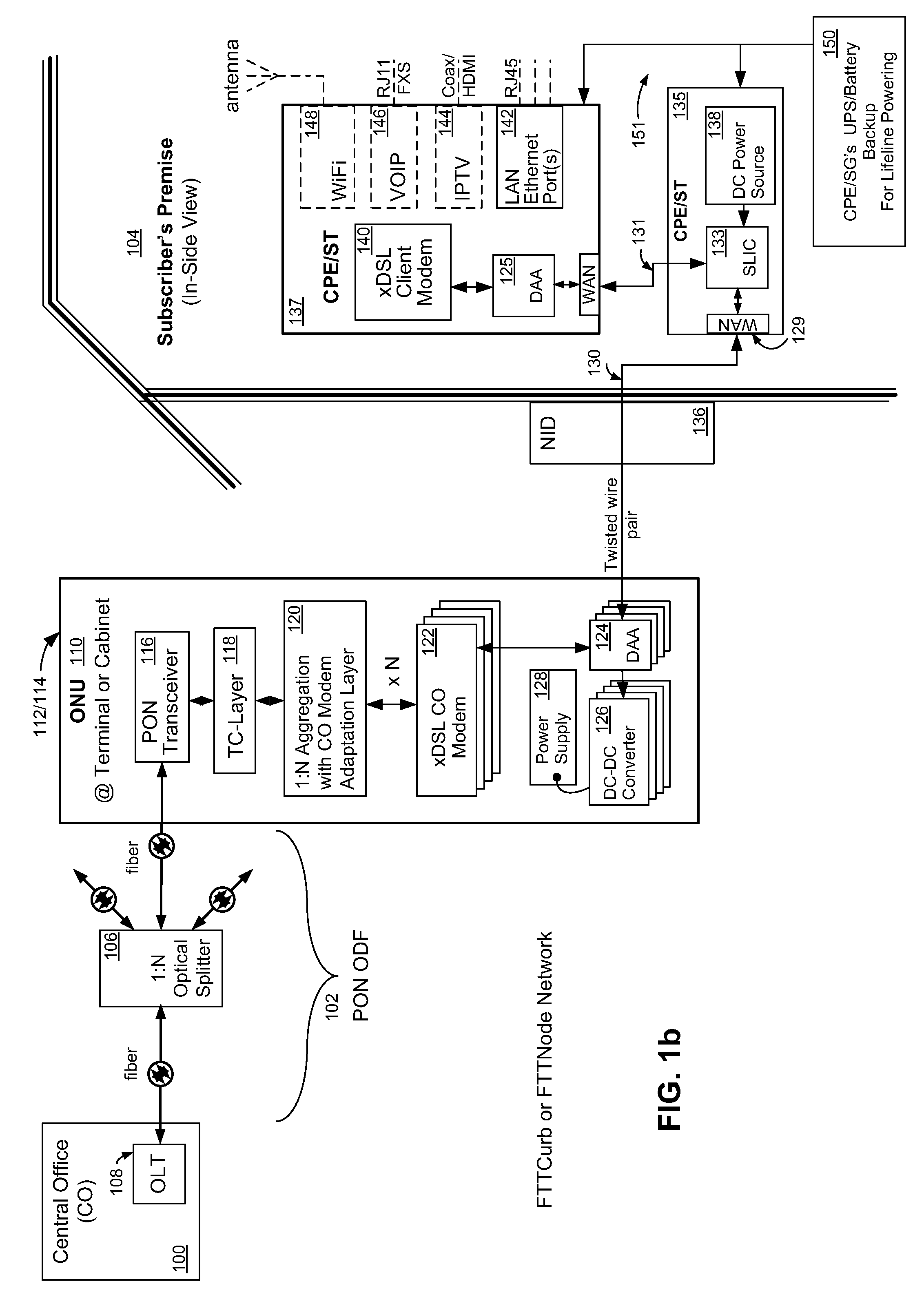
[0045]Referring now to FIG. 1a, wherein like reference numerals designate identical or corresponding parts throughout several views and embodiments; and wherein cascading boxes below a part designates a plurality of such parts, an exemplary embodiment of an electrical power architecture for a fiber optic wide area network is shown incorporating a subscriber-powered network element, according to the present invention. A FTTC or FTTN network using a PON (e.g., B-PON ITU-T G.983, G-PON ITU-T G.984, XG-PON ITU-T G.987, E-PON IEEE 802.3ah, 10G-EPON IEEE 802.3av, WDM-PON, or RFoG SCTE IPS910) connects a central office (CO) 100 at the head end of a passive optical distribution fabric (ODF) 102 to a subscriber premise 104. The subscriber premise 104 may be a residential home, a multi-dwelling unit (MDU), a commercial building, or a cell tower. The passive ODF 102 is comprised of a plurality of passive optical splitters 106 and connectors (not shown). An Optical Line Terminal (OLT) 108, whic...


PUM


Abstract

A system for powering a network element of a fiber optic wide area network is disclosed. When communication data is transferred between a central office (CO) and a subscriber terminal using a network element to convert optical to electrical (O-E) and electrical to optical (E-O) signals between a fiber from the central office and twisted wire pair, coaxial cable or Ethernet cable transmission lines from the subscriber terminal, techniques related to local powering of a network element or drop site by the subscriber terminal or subscriber premise remote powering device are provided. Certain advantages and/or benefits are achieved using the present invention, such as freedom from any requirement for additional meter installations or meter connection charges and does not require a separate power network.

Description

CROSS-REFERENCES TO RELATED APPLICATIONS[0001]This application is filed under 37 C.F.R. §1.53(b)(2) as a continuation-in-part claiming the benefit under 35 U.S.C. §120 of the pending patent application Ser. No. 11 / 764,228, “System and Method For A Subscriber-Powered Network Element”, which was filed by the same inventors on Jul. 17, 2007 claiming the benefit under 37 C.F.R. §1.53(b)(2) of patent application Ser. No. 11 / 369,512 which was filed by the same inventors on Mar. 1, 2006, now abandoned, claiming the benefit under 35 U.S.C. 119(e) of U.S. Provisional Patent Application No. 60 / 657,511 filed on Mar. 1, 2005, now expired, and entirely incorporated herein by reference.FIELD OF THE INVENTION[0002]The invention relates generally to fiber optic communication networks, more specifically to the electrical powering architecture of optical access networks, wide area networks, broadband communications or telecommunication systems.BACKGROUND OF THE INVENTION[0003]With increasing customer...

Claims


Application Information

Patent Timeline
Patent Type & Authority Applications(United States)
IPC IPC(8): H04J14/00
CPCH04M19/08H04B10/808H04B10/00H04B10/27
Inventor SOTO, ALEXANDER I.SOTO, WALTER G.
Owner SOTO ALEXANDER I
Why Eureka
Try Eureka