System and method for a subscriber-powered network element

a subscriber-powered network and subscriber-powered technology, applied in the field of fiber optic communication networks, can solve the problems of not supporting high bandwidth, too large reach and bandwidth limitations, and the added burden of maintaining the multitude of optical to copper drop sites, so as to reduce labor installation time and cost, and cost-effective

Active Publication Date: 2021-03-11
SOTO ALEXANDER IVAN +1
View PDF0 Cites 8 Cited by
  • Summary
  • Abstract
  • Description
  • Claims
  • Application Information

AI Technical Summary

Benefits of technology

[0014]According to the present invention, techniques related to subscriber or reverse powering or backfeeding of a network element or drop site of a wide area access network by a subscriber terminal, adaptor, router, server, gateway, or customer premise equipment (CPE) which combines an electrical power signal or electricity, which may be derived from subscriber mains power (e.g., AC power), with the electrical data communications as a combined electrical WAN signal over the same communication medium connecting the network element or drop site and the subscriber terminal, adaptor, router, server, gateway or CPE are provided. Certain advantages and / or benefits may be achieved using embodiments of the present invention. For example, the embodiments of the present invention have the advantage of being free of any requirement for additional meter installations or meter connection charges. Additionally, embodiments of the present invention have the advantage of reducing labor installation time and costs and enabling subscriber self-installation. Furthermore, embodiments of the present invention do not create a separate power network. The information network and the power network are the same network in that they share the same transmission line (e.g., twisted copper wire pair or twisted wire pair, coaxial cable or Ethernet cable), thus the communication network can be powered in a cost effective and maintainable manner.

Problems solved by technology

Twisted wire pair cable, such as used in plain old telephone services, do not support high bandwidths over a great distance; and while coaxial cables, such as used in cable television services, do a better job, it too has reach and bandwidth limitations.
One major problem with bringing fiber cable within a short distance of a subscriber location is the added burden of maintaining the multitude of optical to copper drop sites.
Optical fiber itself is not capable of carrying the electricity to power these drop sites.
This creates a challenge in planning, distributing and deployment of electricity to power the drop site energy needs.
Increased voltages raise craft safety issues.
Furthermore, there is the 24-hour a day cost of supplying electricity to the power network, as well as regular maintenance and support of the power network itself including regular replacement of batteries for Lifeline services, which are generally located at the CO or head-end.
This results in a large number of battery sites and power access points.
Generally the cost of this type of system is high primarily due to the cost of connecting drop sites to a commercial power source.
This poses a major problem when the monthly energy consumption of a drop site is significantly lower than the minimum charge.
However, its use is limited to areas with direct access to sunlight as the output of solar panels decreases with a reduction in incident solar energy.
Therefore, this strategy cannot be used everywhere.

Method used


Image

  • System and method for a subscriber-powered network element
  • System and method for a subscriber-powered network element
  • System and method for a subscriber-powered network element

Examples


Embodiment Construction

[0053]Reference will now be made in detail to various embodiments of the invention, examples of which are illustrated in the accompanying drawings. While the invention will be described in conjunction with these embodiments, it will be understood that they are not intended to limit the invention to these embodiments. On the contrary, the invention is intended to cover alternatives, modifications and equivalents, which may be included within the spirit and scope of the invention as defined by the appended claims. Furthermore, in the following description of the present invention, numerous specific details are set forth in order to provide a thorough understanding of the present invention. In other instances, well-known methods, procedures, components, and circuits have not been described in detail as not to unnecessarily obscure aspects of the present invention.

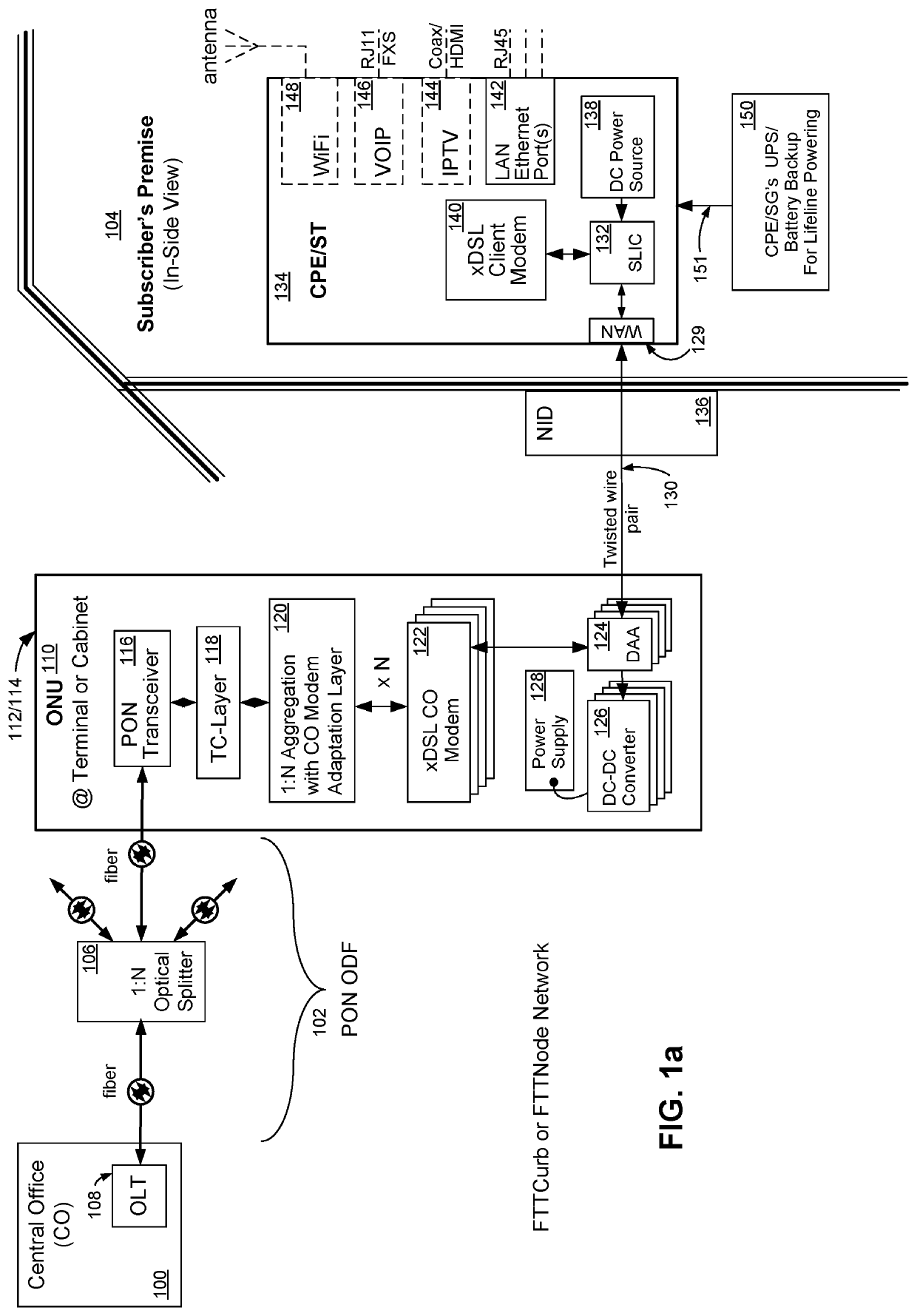
[0054]Referring now to FIG. la, wherein like reference numerals designate identical or corresponding parts throughout severa...


PUM


Abstract

A system for powering a network element of a fiber optic wide area network is disclosed. When communication data is transferred between a central office (CO) and a subscriber terminal using a network element to convert optical to electrical (O-E) and electrical to optical (E-O) signals between a fiber from the central office and twisted wire pair, coaxial cable or Ethernet cable transmission lines from the subscriber terminal, techniques related to local powering of a network element or drop site by the subscriber terminal or subscriber premise remote powering device are provided. Certain advantages and/or benefits are achieved using the present invention, such as freedom from any requirement for additional meter installations or meter connection charges and does not require a separate power network.

Description

CROSS-REFERENCES TO RELATED APPLICATIONS[0001]This application is filed under 37 C.F.R. § 1.53(b) as a continuation claiming the benefit under 35 U.S.C. § 120 of patent application Ser. No. 16 / 557,832, “System and Method For A Subscriber-Powered Network Element”, which was filed by the same inventors on Aug. 30, 2019 claiming the benefit under 35 U.S.C. § 120 of patent application Ser. No. 15 / 396,148, “System and Method For A Subscriber-Powered Network Element”, which was filed by the same inventors on Dec. 30, 2016 claiming the benefit under 37 C.F.R. § 1.53(b)(2) of patent application Ser. No. 14 / 025,804, “System and Method For A Subscriber-Powered Network Element”, which was filed by the same inventors on Sep. 12, 2013 claiming the benefit under 37 C.F.R. § 1.53(b)(2) of patent application Ser. No. 12 / 714,543, “System and Method For A Subscriber-Powered Network Element”, which was filed by the same inventors on Feb. 28, 2010 claiming the benefit under 37 C.F.R. § 1.53(b)(2) of pa...

Claims


Application Information

Patent Timeline
Patent Type & Authority Applications(United States)
IPC IPC(8): H04B10/80H04L12/10H04L12/28H04M19/08H04B10/272H04B10/079
CPCH04B10/808H04B10/806H04L12/10H04B10/07955H04M19/08H04B10/272H04L12/2898
Inventor SOTO, ALEXANDER IVANSOTO, WALTER GLENN
Owner SOTO ALEXANDER IVAN
Why Eureka
Try Eureka