Electromagnetic Swing

a technology of electromagnetic swing and swing, applied in the field of electromagnetic swing, can solve the problems of reducing the power efficiency of only effective current magnetic drive system, and limiting the ability of such swings to control the dynamics of swing motion

Active Publication Date: 2010-06-17
KIDS II INC
View PDF99 Cites 33 Cited by
  • Summary
  • Abstract
  • Description
  • Claims
  • Application Information

AI Technical Summary

Benefits of technology

[0007]According to various other embodiments, the powered children's swing comprises a seat, swing frame, one or more swing arms, a first magnetic component, and second magnetic component. The swing frame supports the seat and defines at least one arcuate support member. The one or more swing arms are rotatably supported on the swing frame and support the seat thereby suspending the seat and permitting the seat to swing along a path. The arcuate support member is positioned adjacent the swing path of the seat and is curved generally parallel to the swing path of the seat. The first magnetic component is supported by the arcuate support member. The second magnetic component is operatively connected to the seat and is configured to move along a path generally parallel to and adjacent to the arcuate support member as the seat swings along its swing path. At least one of the magnetic components comprises an electromagnet configured to selectively generate a magnetic force with the other magnetic component so as to cause the seat to swing along its swing path.

Problems solved by technology

However, current magnetically driven children's swings have a number of drawbacks.
As a result, current magnetic drive systems are only effective when the swing seat is moving away from one of the magnetic components.
This limits the ability of such swings to control the dynamics of the swing's motion and provide a smooth and continuous driving force.
In addition, as the magnetic force between two magnetic objects decreases over distance, significant gaps between the magnetic drive components of current swings reduces the power efficiency of their magnetic drive systems.

Method used


Image

  • Electromagnetic Swing
  • Electromagnetic Swing
  • Electromagnetic Swing

Examples


Embodiment Construction

[0028]The present invention now will be described more fully hereinafter with reference to the accompanying drawings, in which embodiments of the invention are shown. This invention may, however, be embodied in many different forms and should not be construed as limited to the embodiments set forth herein; rather, these embodiments are provided so that this disclosure will be thorough and complete, and will fully convey the scope of the invention to those skilled in the art. Like numbers refer to like elements throughout.

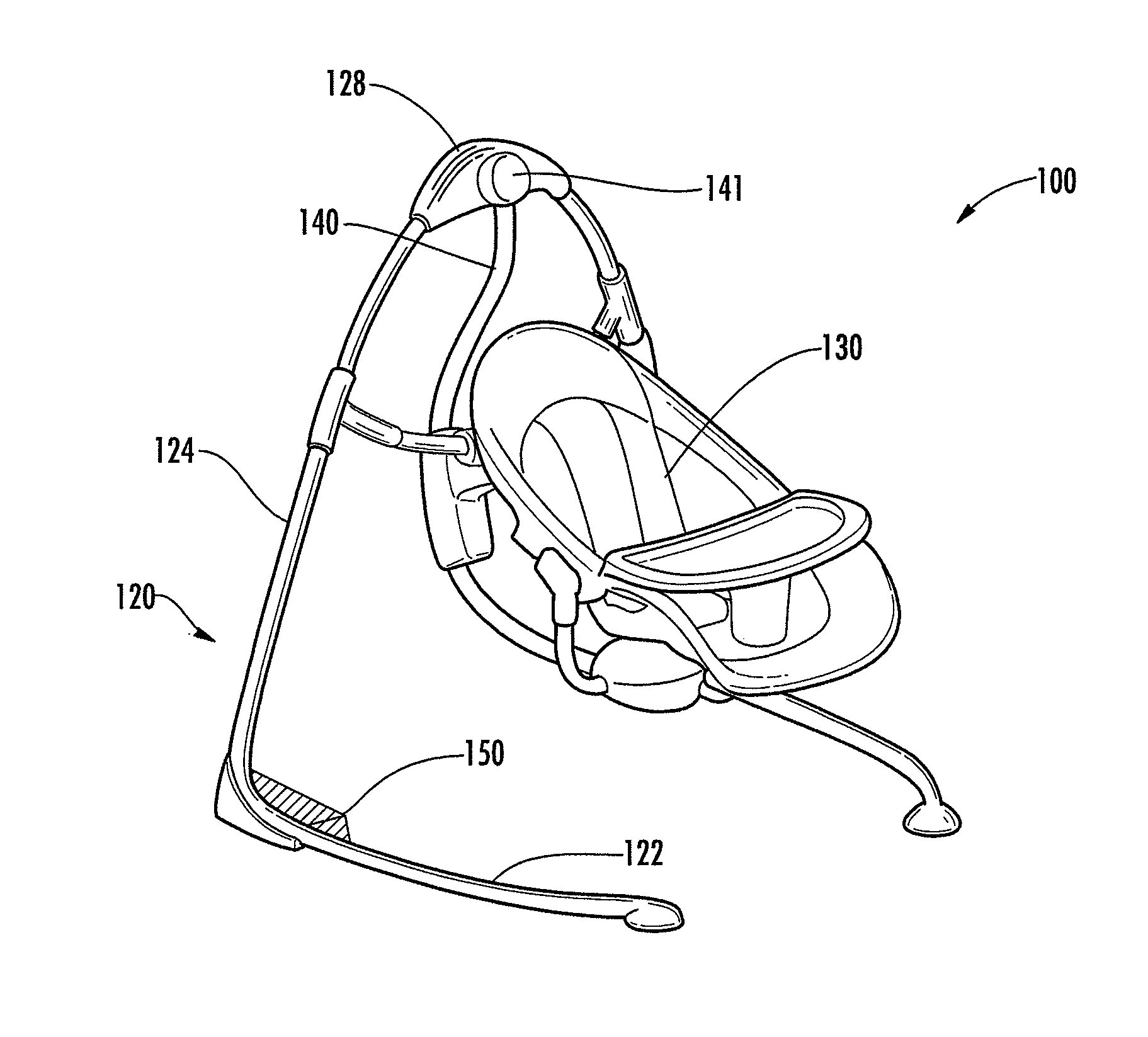
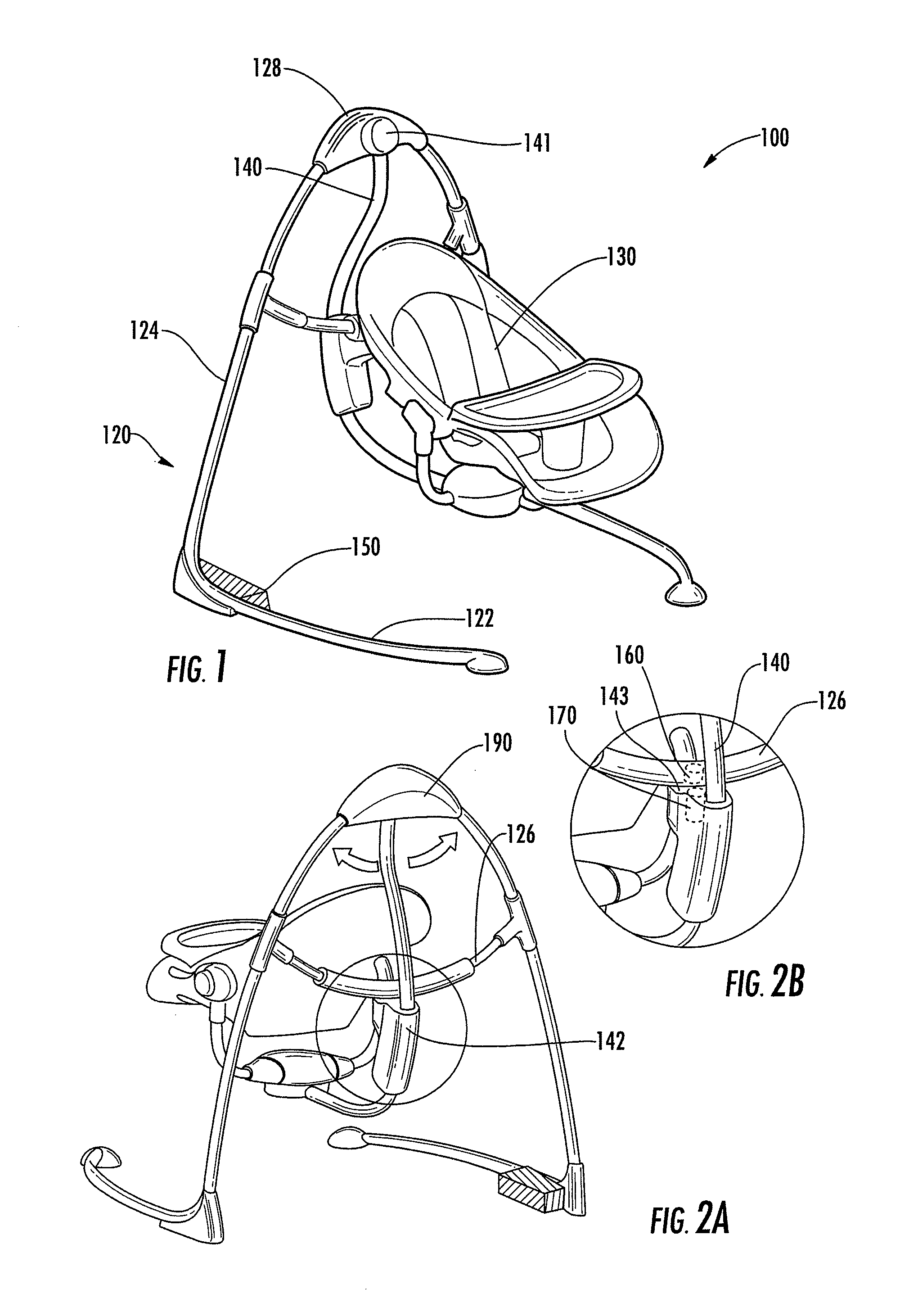
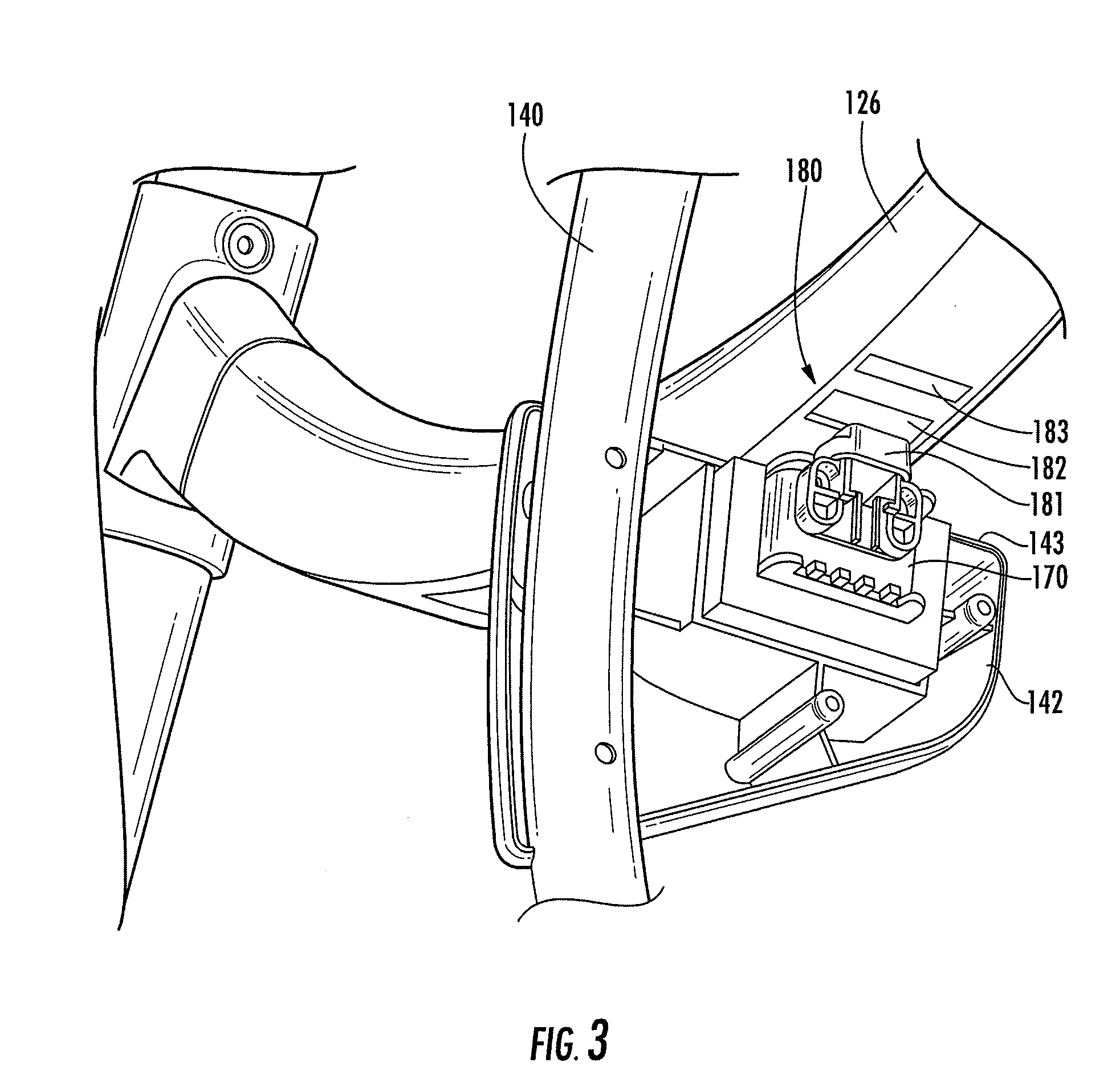
[0029]As described above, various embodiments of the present invention are directed to a powered children's swing providing a seat that is driven along a swing path with controlled amplitude by a magnetic drive system. According to various embodiments, the powered children's swing generally includes a swing frame, seat, swing arm, magnetic drive system, power supply, swing motion sensor, and swing control circuit. As described above, in one embodiment, the magnetic ...


PUM


Abstract

Various embodiments of the present invention are directed to a powered children's swing. In various embodiments, the swing includes a seat, swing frame, one or more swing arms, a first magnetic component, second magnetic component, swing motion sensor, and swing control circuit. The magnetic components are configured to generate a magnetic force that drives the seat along a swing path. The swing control circuit is configured to control the magnetic components based at least on input from the swing motion sensor and generate control signals causing the seat to swing with a substantially constant amplitude as specified by a user.

Description

CROSS-REFERENCE TO RELATED APPLICATIONS[0001]This application claims priority from provisional U.S. Application No. 61 / 121,996 entitled “Solenoid Swing,” which was filed on Dec. 12, 2008 and is herein incorporated by reference. This application also claims priority from provisional U.S. Application No. 61 / 138,286 entitled “Magnet Motor Controller,” which was filed on Dec. 17, 2008 and is herein incorporated by reference.BACKGROUND OF THE INVENTION[0002]Children's swings are typically used to entertain and put to sleep children, including infants, by providing a seat that swings smoothly along an arcuate path. Powered children's swings are particularly advantageous as they are configured to automatically swing a seat without the need for a parent or child to continuously provide a motive force to keep the seat in motion. Such powered children's swings are known to be powered in various configurations by motors (e.g., a direct current motor) via a mechanical linkage to the swing seat....

Claims


Application Information

Patent Timeline
Patent Type & Authority Applications(United States)
IPC IPC(8): A63G9/16G05B15/00
CPCA47D13/105H02P25/027A63G9/16H02P25/032A47D9/057
Inventor GILBERT, DAVIDBURNS, STEPHEN R.JACKSON, PETER D.SIMONS, CHARLESRU, CHEN JING
Owner KIDS II INC
Why Eureka
Try Eureka