Optical depilation apparatus

a technology of optical depilation and optical lens, which is applied in the field of optical depilation apparatus, can solve the problems of flashes that can enter the eyes of users or other people, flashes that can be unintentionally and erroneously emitted, and the safety measures taken to prevent light leakage to the outside are insufficient, so as to achieve the effect of high safety and facilitate maintenan

Inactive Publication Date: 2010-06-17
PANASONIC CORP
View PDF9 Cites 17 Cited by
  • Summary
  • Abstract
  • Description
  • Claims
  • Application Information

AI Technical Summary

Benefits of technology

[0006]It is another object of the present invention to provide an optical depilation apparatus of high safety, in which the light irradiating the skin during the depilation treatment can be prevented from leaking and entering the eyes, maintenance can be facilitated, and the light for depilation can be prevented from being emitted at an unintended time and entering the eyes.

Problems solved by technology

However, in the above-described optical depilation apparatus, safety measures taken to prevent the light from leaking to the outside are insufficient.
In a case where a flashlamp generating flashes is used as the light source, the flashes easily leak to the outside and can enter the eyes of the user or other people.
Furthermore, the flashes can be unintentionally and erroneously emitted when the optical depilation apparatus is maintained and the flashes can enter the eyes of the user or other people.

Method used


Image

  • Optical depilation apparatus
  • Optical depilation apparatus
  • Optical depilation apparatus

Examples


Embodiment Construction

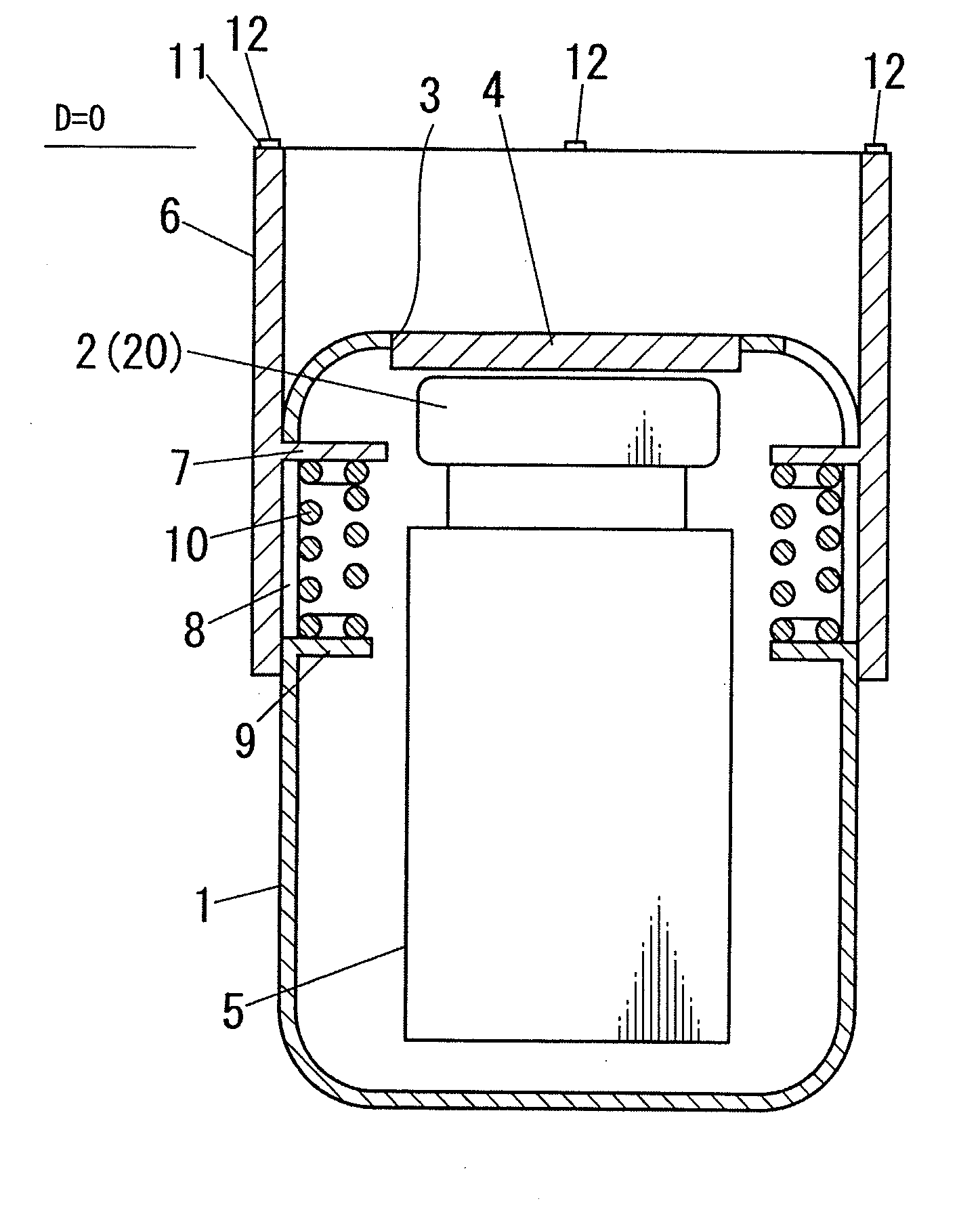
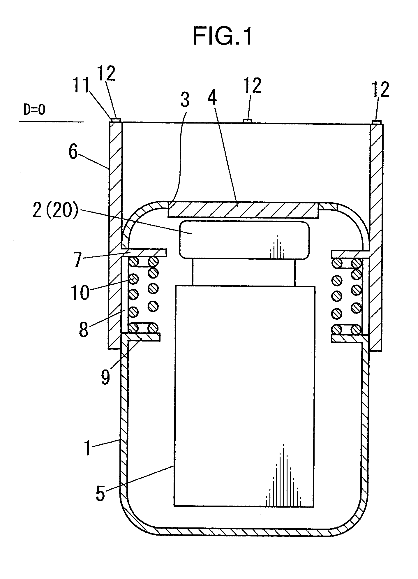
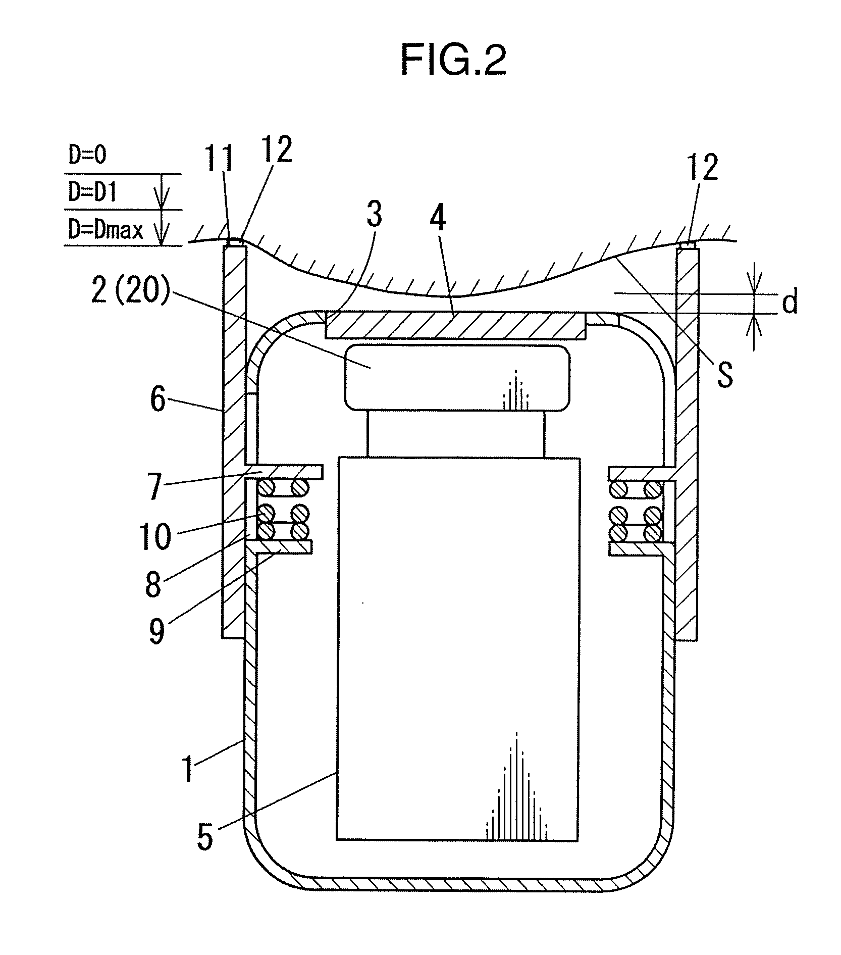
[0020]The embodiments of the present invention will be described below with reference to the appended drawings. FIGS. 1 to 7 illustrate schematically the entire structure of the optical depilation apparatus according to one embodiment of the invention.

[0021]The optical depilation apparatus of the present embodiment is provided with a box-shaped apparatus body 1 that can be grasped by one hand. A flashlight 2 that is used as a light source unit 20 is accommodated in the apparatus body 1. The flashlight 2 is composed of a xenon lamp. A light irradiation port 3 that links the inside of the apparatus body 1 with the outside is opened in a position close to the flashlight 2 at the distal end of the apparatus body 1. This light irradiation port 3 is disposed so as to be opposite the flashlight 2. A transparent lamp cover 4 is fitted in the light irradiation port 3. The lamp cover 4 is provided at the apparatus body 1 so that the outer surface of the lamp cover 4 is exposed. The flashlight...


PUM


Abstract

An optical depilation apparatus of high safety is provided, in which the light irradiating the skin during the depilation treatment can be prevented from leaking and entering the eyes, maintenance can be facilitated, and the light for depilation can be prevented from being emitted at an unintended time and entering the eyes. The apparatus for performing depilation by irradiating the skin with light includes: an apparatus body; a light source unit provided at the apparatus body and capable of emitting the light for irradiating the skin; a light shielding pipe having a skin contact surface at an end surface on the side opposite to the apparatus body in the axial direction of the light shielding pipe and is attached detachably to the apparatus body so as to surround a portion of the apparatus body which radiates light emitted from the light source unit; and a control circuit that disables the emission of light from the light source unit in a state in which the light shielding pipe is not attached to the apparatus body.

Description

TECHNICAL FIELD[0001]The present invention relates to an optical depilation apparatus that performs depilation by irradiating skin with light from a light irradiation unit.BACKGROUND ART[0002]An optical depilation apparatus in which hair papilla is heated by transferring light energy emitted by a laser diode or a flashlamp to the hair, thereby making it difficult for nutrients to reach the hair, is known as a device for conducting depilation. In such an optical depilation apparatus, the skin with hairs is required to be irradiated with light from the direction perpendicular to the skin. Accordingly, in the optical depilation apparatus disclosed in Patent Document 1 or Patent Document 2 below, a plurality of contact sensors are disposed in positions surrounding the laser beam irradiation portion of the distal end of the apparatus, the optical depilation apparatus is determined to have a perpendicular posture when the contact sensors detect contact with the skin, and the laser beam ir...

Claims


Application Information

Patent Timeline
Patent Type & Authority Applications(United States)
IPC IPC(8): A61B18/18
CPCA61B18/203A61B2018/00452A61B2018/00476A61B2019/465A61B2019/306A61B2019/409A61B2018/1807A61B2090/036A61B2090/0436A61B2090/049A61B2090/065
Inventor FUJIKAWA, SHOJI
Owner PANASONIC CORP
Why Eureka
Try Eureka