Injection Flame Burner and Furnace Equipped With Same Burner and Method for Generating Flame
- Summary
- Abstract
- Description
- Claims
- Application Information
AI Technical Summary
Benefits of technology
Problems solved by technology
Method used
Image

Examples
first example of transformed embodiment
1. First Example of Transformed Embodiment
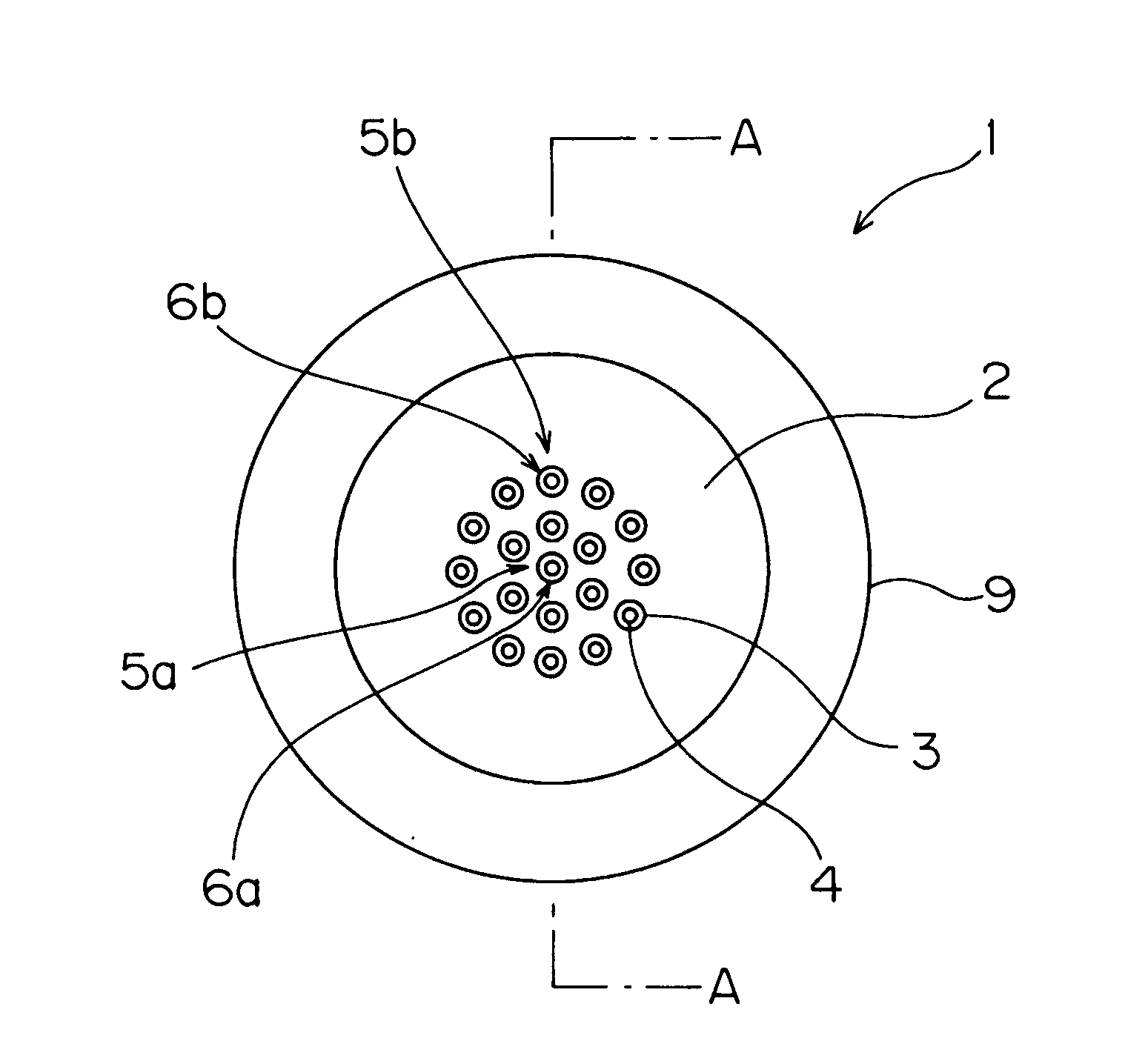
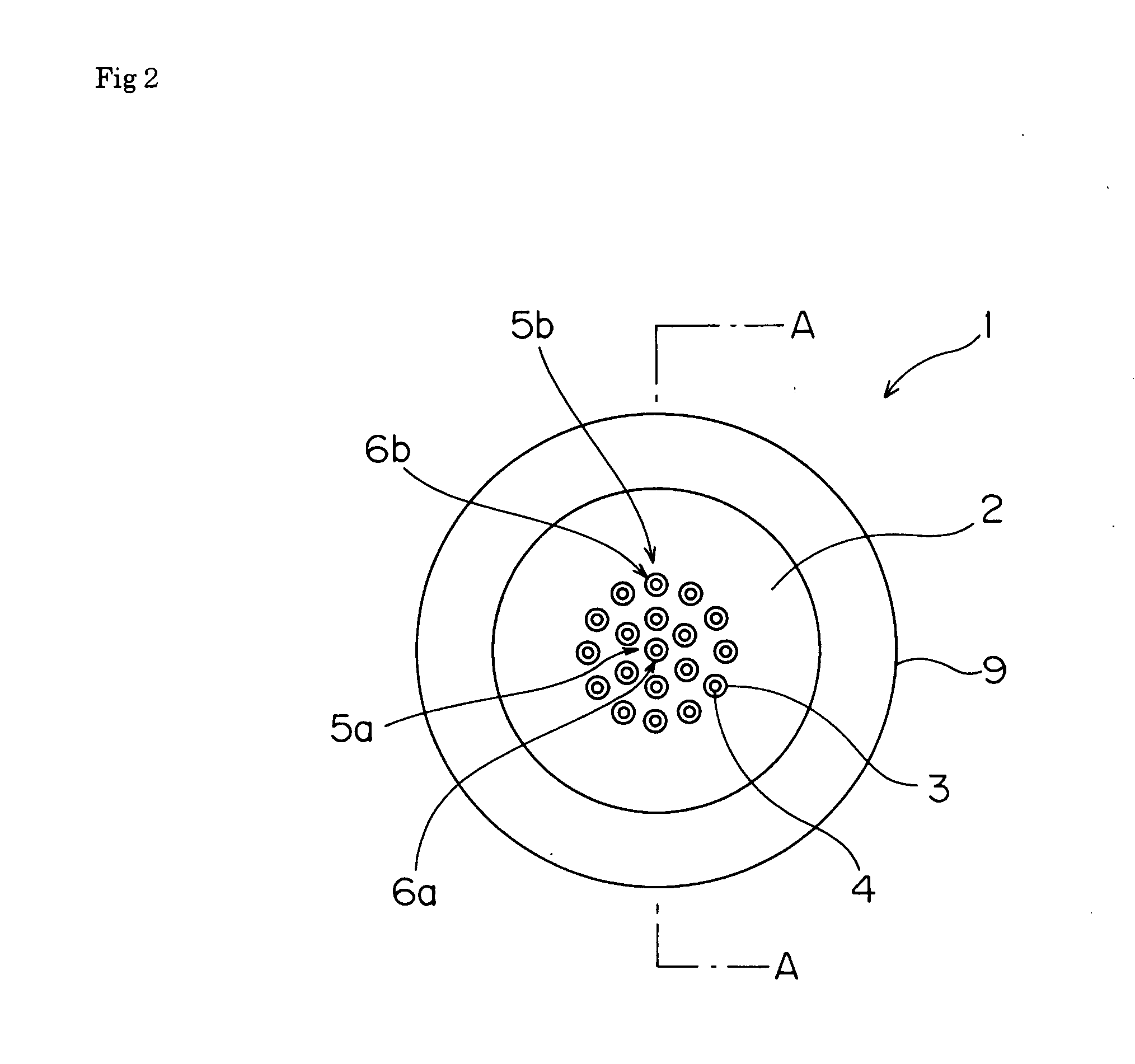
[0035]This example is a transformed embodiment of the injection nozzle (5), and it is explained according to FIG. 1-FIG. 6. FIG. 7 is a plan view of the injection flame burner while the refrigerator is omitted. FIG. 8 is an illustration of gas being ejected wherein each reference numeral corresponds to that shown in FIG. 1-FIG. 6.
[0036]In the injection nozzle (5) three pieces of the main nozzles (5a) are formed at the center, and at the same time the plural sub nozzles in double lines surrounding the main nozzles (5a) in the concentric circle.
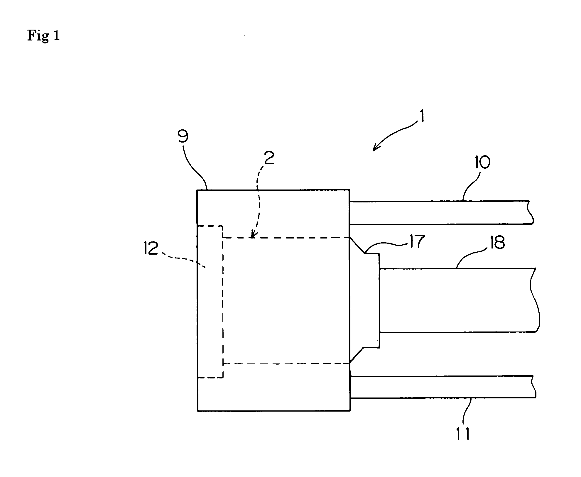
[0037]The injection flame burner (1) includes the outer tube (3) and the inner tube (4) is formed coaxially with the outer tube (3), and a plurality of double structure injection nozzles (5) that include the outer tube (3) that injects hydrogen gas and the inner tube (4) that injects oxygen gas is established while the injection port (6) is located on the disk-like surface lid (12). The three main nozzl...
PUM
 Abstract
Description
Claims
Application Information
PatSnap Eureka turns technology decisions into work you can execute. Powered by our Innovation Knowledge Graph, it runs expert workflows across engineering, life sciences, materials and intellectual property. Get your review-ready output in minutes.


