Pneumatic tire

a technology of pneumatic tires and spherical plates, which is applied in the direction of heavy-duty vehicles, vehicle components, non-skid devices, etc., can solve the problems of difficult uneven wear, and even wear, so as to improve uneven wear resistance, improve wet performance, and enhance the edge effect and drainage

Inactive Publication Date: 2010-06-24
BRIDGESTONE CORP
View PDF9 Cites 10 Cited by
  • Summary
  • Abstract
  • Description
  • Claims
  • Application Information

AI Technical Summary

Benefits of technology

[0021]Here, the reason why a difference in depth between the rib edge side portion in the sips and the runner groove is set to not less than 3 mm is because the edge effect and drainage cannot be sufficiently secured in the middle stage of wear and thereafter, unless the difference in depth between the rib edge side portion in the sips and the runner groove reaches 3 mm. Moreover, the reason why the difference in depth between the rib edge side portion in the sipe and the runner groove is set to not more than 8 mm is because, if the difference in depth between the rib edge side portion in the sips and the runner groove exceeds 8 mm, circumferential r...

Problems solved by technology

Thus, due to shear deformation in kicking out, uneven wear such as heel-and-toe (hereinafter abbreviated as H&T) wear is likely to occur.
The...

Method used


Image

  • Pneumatic tire
  • Pneumatic tire
  • Pneumatic tire

Examples


examples

[0051]Examples of the present invention will be described.

(1) Test Method

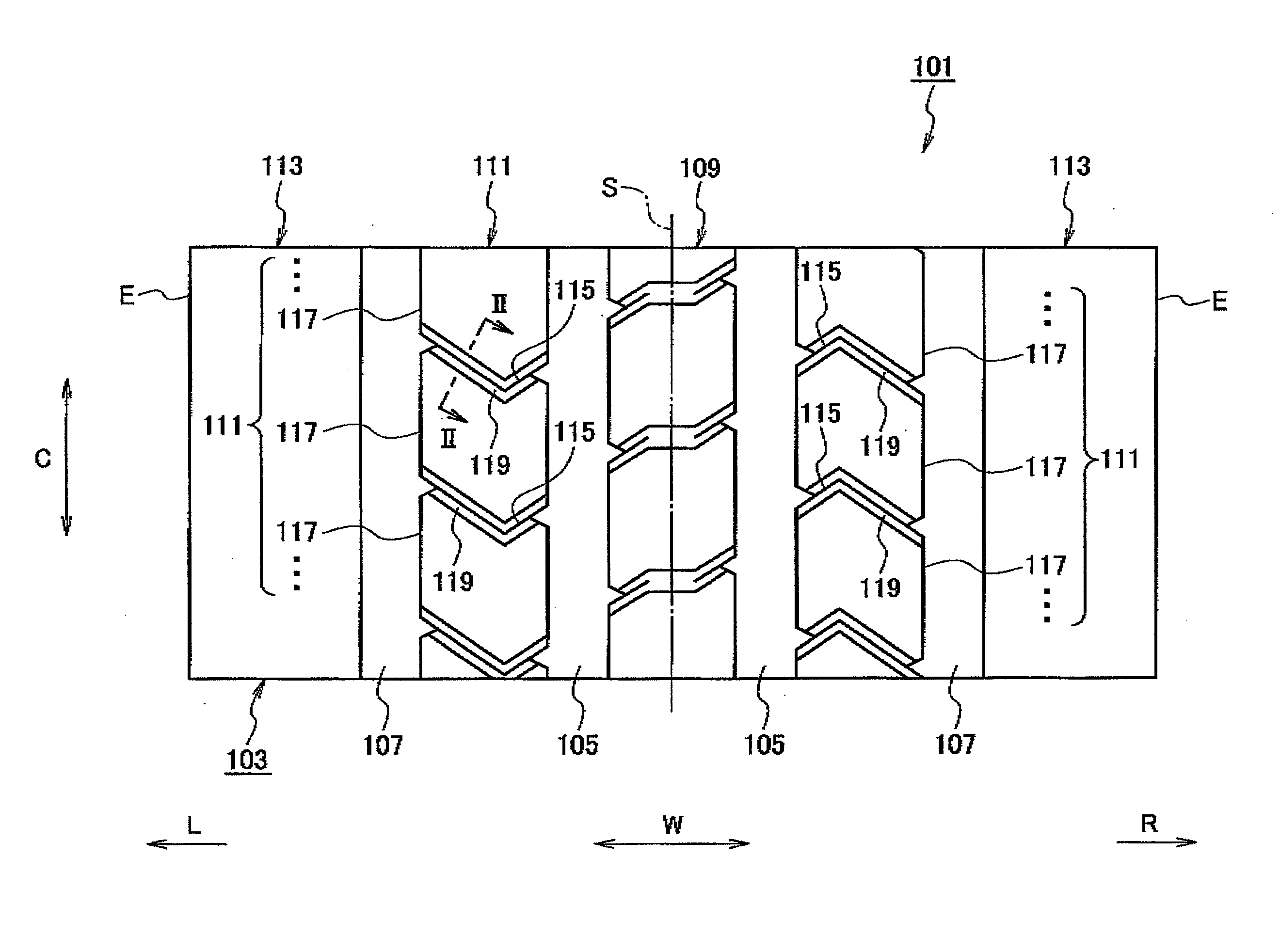
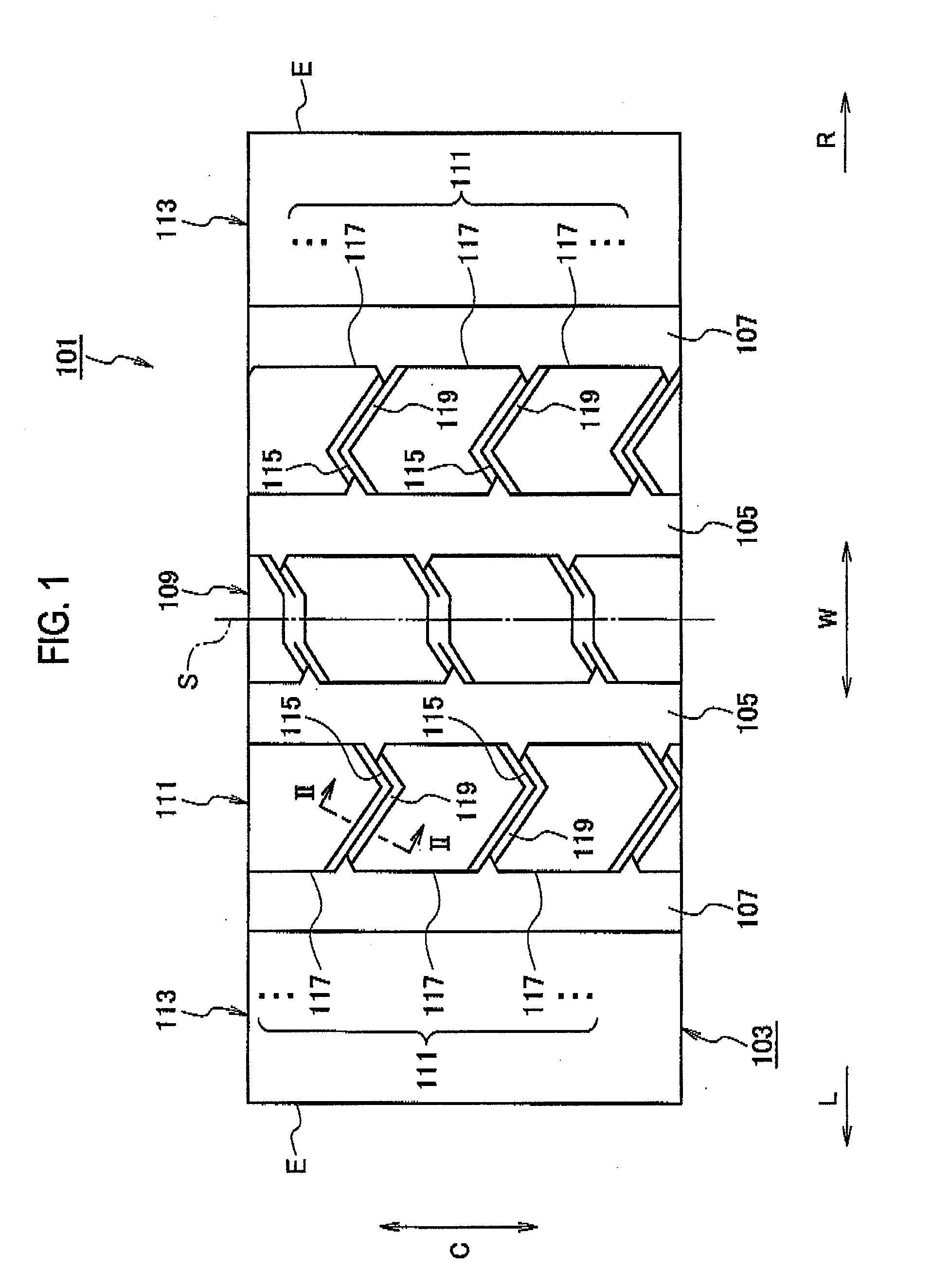
[0052]As Examples 1 to 6, products of the pneumatic tire 1 according to the embodiment shown in FIG. 3 are used, and each product is set to have a pattern configuration as shown in Table 1 for each specification. Moreover, as Comparative Example 1, a product of the pneumatic tire 101 according to the embodiment shown in FIG. 1 is used and similarly set to have a pattern configuration as shown in Table 1.

[0053]Thereafter, for each of Examples 1 to 6 and Comparative Example 1, (a) an uneven wear (H&T step) measuring test and (b) a feeling evaluation test having combined turning and braking tests on a wet road surface are conducted. Note that test conditions are as follows.

(a) Uneven Wear (H&T Step) Measuring Test

[0054]Size of tire used: 315 / 80R22.5[0055]Size of rim used: 9.00×22.5[0056]Set inner pressure of tire: 825 kPa[0057]Vehicle type: 4×2 tractor, pulling three-axle trailer[0058]Mounting position: Front whee...


PUM


Abstract

A plurality of ribs (9, 11 and 18) extending in a tire circumferential direction (C) are defined in a tire width direction (W) by a plurality of circumferential main grooves (5 and 7). In two or more second ribs (11), a plurality of sipes (19) are formed so as to be spaced apart in the tire circumferential direction (C) and to cut across the ribs. By the plurality of sipes (19), the two or more second ribs (11) are divided into a plurality of divided ribs (21). All intersection angle portions on one side in the tire circumferential direction (C) in each of the divided ribs (21) are formed to have obtuse angles. Only on one side in the tire circumferential direction (C) in each of the divided ribs (21), a runner groove (23) communicated with the corresponding sips (19) is formed so as to cut across the second rib (11).

Description

TECHNICAL FIELD [0001]The present invention relates to a pneumatic tire achieving a good balance between wet performance and uneven wear resistance.BACKGROUND ART [0002]With reference to FIGS. 1 and 2, a conventional technique will be described.[0003]Here, FIG. 1 is a planar development view of a part of a tread in a pneumatic tire according to a conventional embodiment. FIG. 2 is a view along the line II-II in FIG. 1. Note that, in the figure, “L” indicates a left direction and “R” indicates a right direction.[0004]As shown in FIG. 1, in a center portion of a tread 103 in a pneumatic tire 101, a pair of center circumferential main grooves 105 extending in a tire circumferential direction C are provided so as to sandwich a tire equator line S therebetween. Moreover, in shoulder portions of the tread 103, a pair of shoulder circumferential main grooves 107 extending in the tire circumferential direction C are provided so as to sandwich the pair of center circumferential main grooves ...

Claims


Application Information

Patent Timeline
IPC IPC(8): B60C11/04B60C11/12
CPCB60C11/0306B60C11/04B60C11/125B60C11/1263B60C2200/06
Inventor HONBOU, YOUICHI
Owner BRIDGESTONE CORP
Why Eureka
Try Eureka