Poppet valve operated by an electrohydraulic poppet pilot valve

a pilot valve and electrohydraulic technology, which is applied in the direction of valve operating means/release devices, mechanical equipment, transportation and packaging, etc., can solve the problems of inability to operate this type of electrohydraulic valve, the stroke of the poppet is incrementally less than the stroke of the solenoid, and the speed of the poppet decreases rapidly with the increase of the poppet siz

Active Publication Date: 2010-06-24
HUSCO INT INC
View PDF24 Cites 38 Cited by
  • Summary
  • Abstract
  • Description
  • Claims
  • Application Information

AI Technical Summary

Benefits of technology

[0013]An electrohydraulic pilot valve controls flow of fluid between the primary control chamber and the release passage, and has an inlet connected to the primary control chamber and an outlet connected to the release passage. The electrohydraulic pilot valve includes a pilot poppet which controls fluid flow from the inlet to the outlet in response to pressure in a pilot control chamber. An electrically operated sub-pilot valve selectively opens to produce a decrease in the pilot control chamber pressure, which thereby causes the pilot poppet to open a path between the inlet and the outlet.

Problems solved by technology

The functionality of this type of electrohydraulic valve is limited to a relationship between the solenoid force and control chamber flow.
While a smaller control chamber flow is still sufficient to position a substantially larger poppet, the speed of the poppet decreases rapidly with increases in poppet size.
Another drawback is that the stroke of the poppet is incrementally less than the stroke of the solenoid.
In addition, enlarging the control orifice resulted in a non-linear relationship between the fluid pressure and flow and the electric current applied to the solenoid, which non-linear relationship adversely affected accurate control.

Method used


Image

  • Poppet valve operated by an electrohydraulic poppet pilot valve
  • Poppet valve operated by an electrohydraulic poppet pilot valve
  • Poppet valve operated by an electrohydraulic poppet pilot valve

Examples


Embodiment Construction

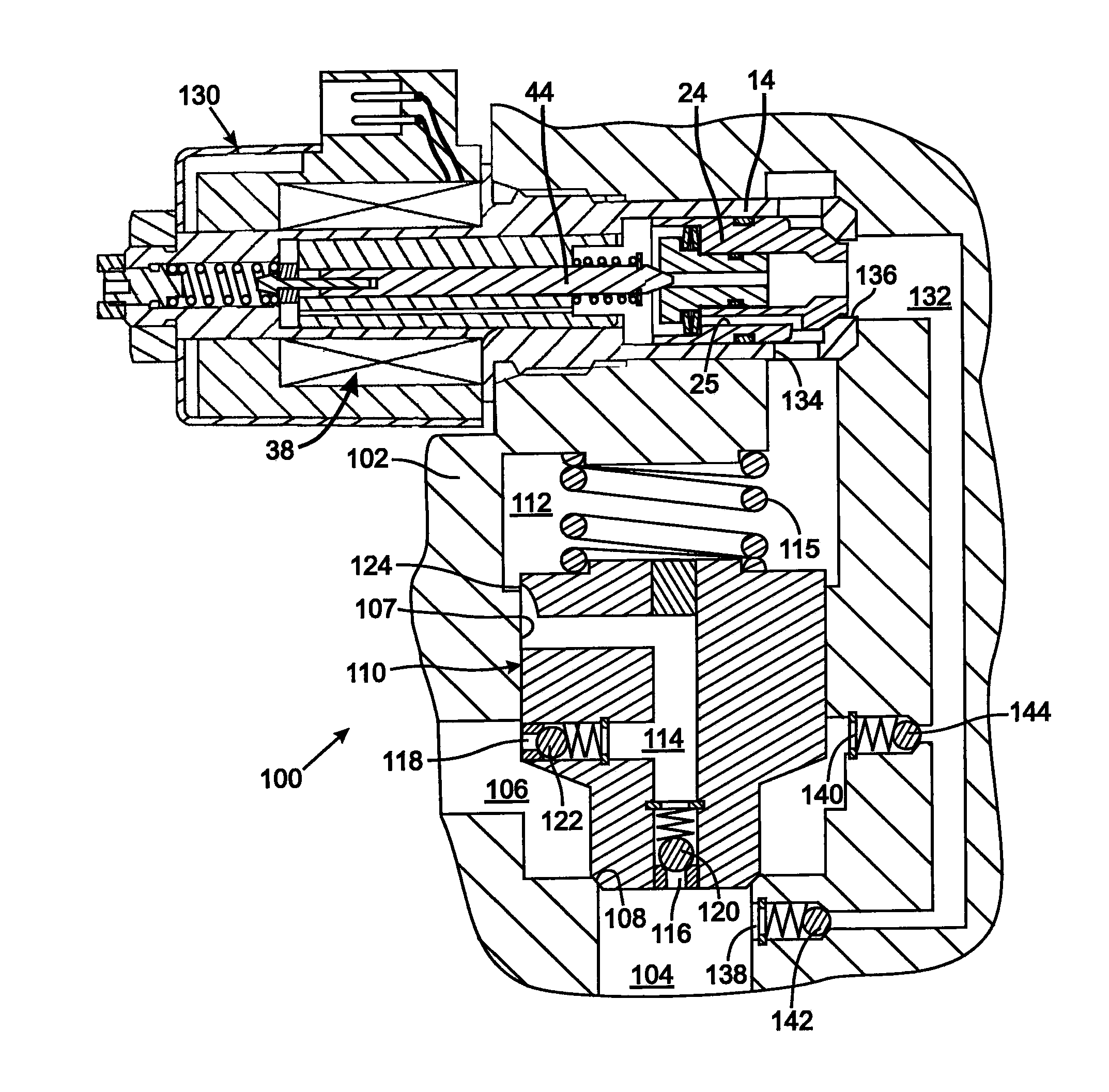
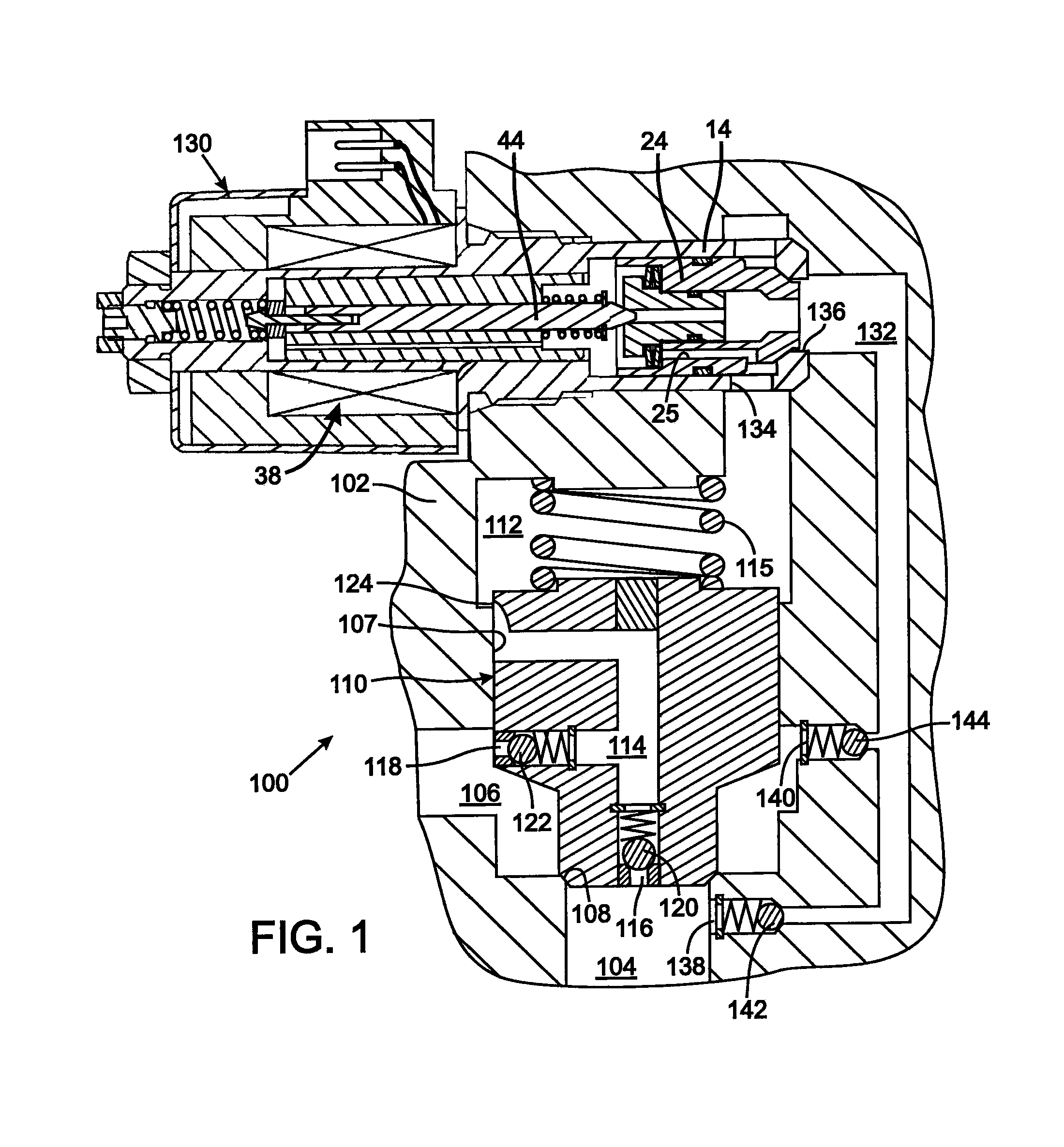
[0023]With initial reference to FIG. 1, a bidirectional control valve 100 has a body 102 with a first port 104 and a second port 106 opening into a primary bore 107. A valve seat 108 is located in between the first and second ports 104 and 106. A main poppet 110 is slidably received within the body 102 and selectively engages the valve seat 108 to close the fluid path between the first and second ports 104 and 106. The main poppet 110 can slide away from engagement with the valve seat 108 to open a flow path between the first and second ports 104 and 106. Movement of the main poppet, as will be described in greater detail herein, is determined by the main spring 115 and relationship of pressures in the first and second ports 104 and 106 and a primary control chamber 112 located on the remote side of the main poppet 110 from the valve seat 108.

[0024]The main poppet 110 has a passageway 114 with a first opening 116 into the first port 104 and a second opening 118 into the second port ...


PUM


Abstract

A control valve includes a main poppet that moves in response to pressure in a primary control chamber and thereby controls the flow of fluid through a valve seat between first and second ports. A passageway extends between the second port and the primary control chamber and includes a variable flow restriction that decreases as the main poppet moves away from the valve seat. An electrohydraulic pilot valve has a pilot poppet which controls fluid flow from the primary control chamber to the first port in response to pressure in a pilot control chamber. A sub-pilot valve selectively releases pressure in the pilot control chamber to operate the pilot poppet to open and close a path between the inlet and the outlet. Using an electrohydraulic pilot valve enables the main poppet to operate quickly in controlling large fluid flow rates. Unidirectional and bidirectional versions of the control valve are described.

Description

CROSS-REFERENCE TO RELATED APPLICATIONS[0001]This application claims benefit of U.S. Provisional Patent Application No. 61 / 139,655 filed on Dec. 22, 2008.STATEMENT REGARDING FEDERALLY SPONSORED RESEARCH OR DEVELOPMENT[0002]Not ApplicableBACKGROUND OF THE INVENTION[0003]1. Field of the Invention[0004]The present invention relates to a pilot operated hydraulic valves and more particularly to electrically operated pilot valves.[0005]2. Description of the Related Art[0006]A wide variety of machines have moveable components which are operated by an hydraulic actuator, such as a cylinder and piston arrangement, that is controlled by a hydraulic valve. Traditionally, the hydraulic valve was manually operated by the machine operator. There is a present trend away from manually operated hydraulic valves toward electrical controls and the use of solenoid valves.[0007]Application of pressurized hydraulic fluid from a pump to the actuator can be controlled by a set of proportional pilot operate...

Claims


Application Information

Patent Timeline
Patent Type & Authority Applications(United States)
IPC IPC(8): F16K31/36F16K31/12F15B13/01
CPCF15B13/0405F16K31/406F15B13/0433Y10T137/7764
Inventor PFAFF, JOSEPH L.
Owner HUSCO INT INC
Why Eureka
Try Eureka