Wind Turbine

a wind turbine and turbine blade technology, applied in the direction of electric generator control, vessel construction, marine propulsion, etc., can solve the problem of dangerous access to the hub, and achieve the effect of reasonable bearing cos

Active Publication Date: 2008-11-06
XEMC VWEC B V I O
View PDF3 Cites 61 Cited by
  • Summary
  • Abstract
  • Description
  • Claims
  • Application Information

AI Technical Summary

Benefits of technology

[0011]In accordance with an embodiment the wind turbine comprises a front bearing (31) that has a bearing diameter which is between 0.40 times and 0.70 times the diameter of the connection flange (8). In this way the first bearing is sufficiently stiff while its diameter is not too large, so that the costs of the bearing remain reasonable.
[0012]In accordance with an embodiment the wind turbine comprises a cylindrical outer shell (9) and if app

Problems solved by technology

The disadvantage of the known wind turbine is that the access to the hub is dangerous as the access path to the hub is either outside the nacelle whic

Method used


Image

  • Wind Turbine
  • Wind Turbine
  • Wind Turbine

Examples


Embodiment Construction

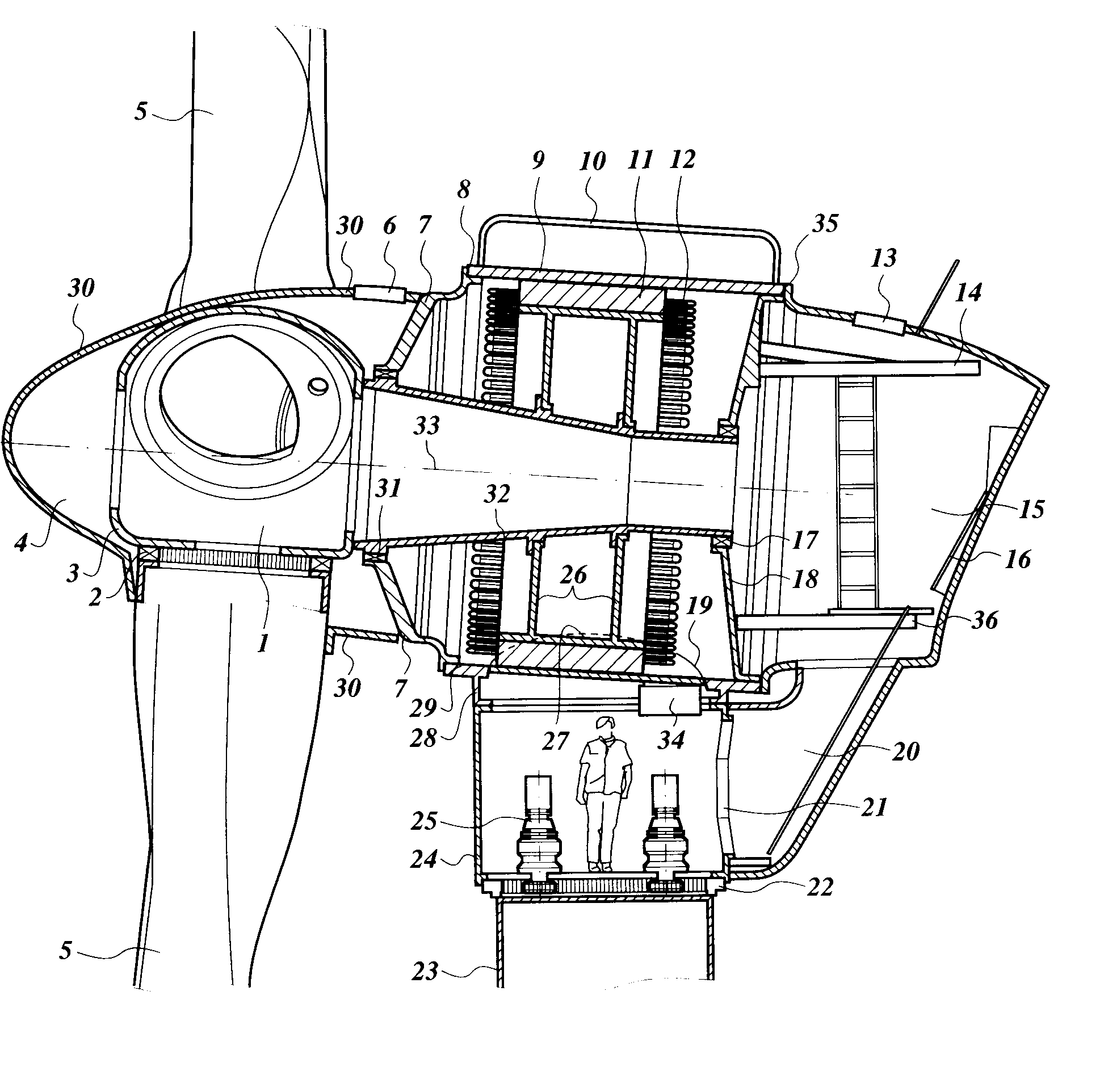
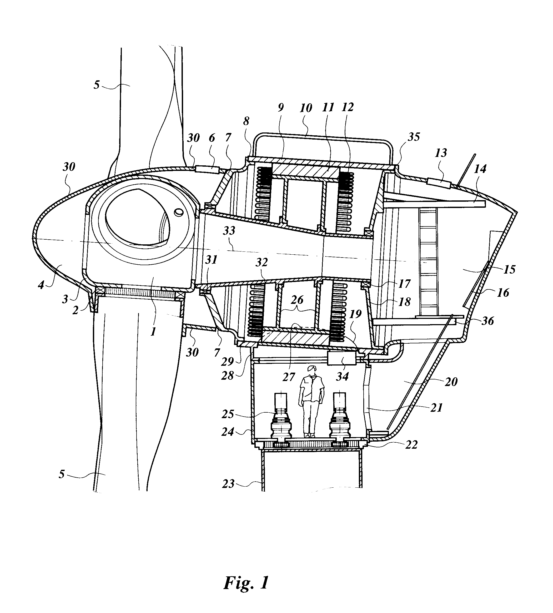
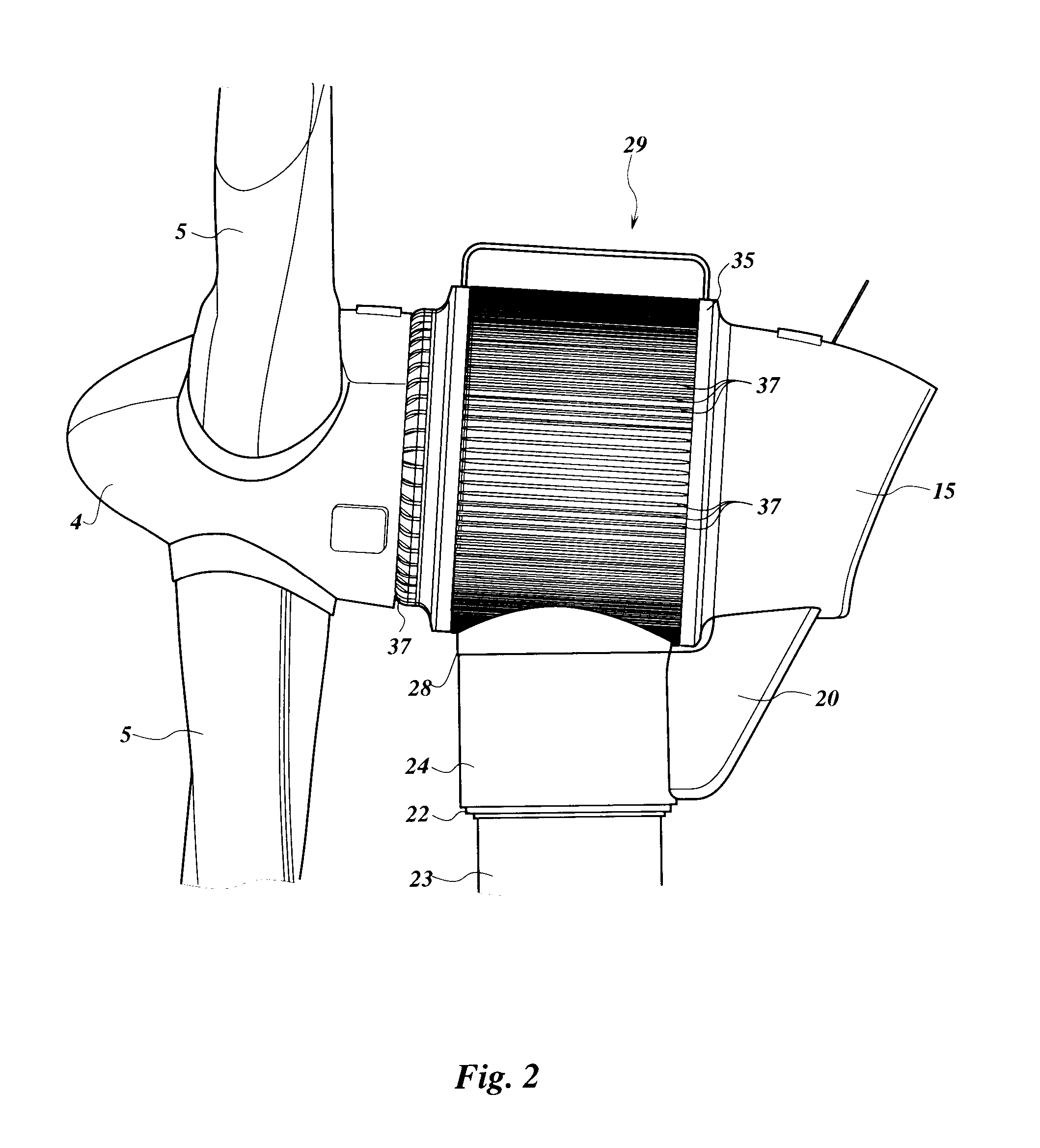
[0018]A yaw bearing 22 is mounted on a tower 23. In the shown embodiment the tower 23 is a cylindrical or slightly conical pipe which is mounted on a foundation. The tower 23 can have different shapes such as a truss. The yaw bearing 22 supports a cylindrical shell 24 which is coupled via a connecting flange 28 to an outer shell 9 of a nacelle 29. The cylindrical shell 24 has a height of approximately 2 meter, so that above the yaw bearing 22 there is sufficient room for an operator to stand. In the cylindrical shell 24 a yaw drive 25 is mounted on gear teeth that are part of the yaw bearing 22 for rotating the nacelle 29 so that a rotation axis 33 of a hub 3 with blades 5 can be directed in the direction of the wind that drives the blades 5 of the wind turbine. The cylindrical shell 24 and / or the connecting flange 28 have a diameter that is more than 50% or approximately 60% of the diameter of the outer shell 9, so that the cylindrical shell 24 and / or the connecting flange 28 stiff...


PUM


Abstract

The invention concerns a wind turbine comprising a vertical tower with a yaw bearing, a nacelle on top of the yaw bearing, a hub with blades rotatable around a more or less horizontal rotation axis. The nacelle has a generator and a control room, whereby the generator comprises a rotor with a rotor shaft supported on two rotor bearings carrying the hub, and a stator comprising a cylindrical outer shell with a stator diameter that is approximately equal to the diameter of the nacelle and which outer shell has at its ends a front cover plate and a back cover plate each with a rotor bearing for supporting the rotor shaft. In accordance with the invention the rotor shaft is hollow and the hollow hub is accessible from the control room through the hollow rotor shaft.

Description

CROSS-REFERENCE TO RELATED APPLICATIONS[0001]The present application claims priority from European patent application no. 07107167, filed Apr. 27, 2007, the content of which is incorporated herein by reference.FIELD OF THE INVENTION[0002]The invention concerns a wind turbine comprising a vertical tower with a yaw bearing (22), a nacelle (29) on top of the yaw bearing, a hub (3) with blades (5) rotatable around a more or less horizontal rotation axis (33), the nacelle comprising a generator and a control room (15), whereby the generator comprises a rotor (27) with a rotor shaft (32) supported on two rotor bearings (17,31) carrying the hub, and a stator (11) comprising a cylindrical outer shell with a stator diameter that is approximately equal to the diameter of the nacelle and which outer shell has at its ends a front cover plate (7) and a back cover plate (18) each with a rotor bearing for supporting the rotor shaft characterized in that the rotor shaft (32) is hollow and the hollo...

Claims


Application Information

Patent Timeline
IPC IPC(8): F03D9/00F03D11/00
CPCF03D1/0666F03D7/02F03D11/0008Y02E10/726Y02E10/721Y02E10/722Y02E10/723F05B2240/61F03D80/70Y02E10/72F03D1/0658
Inventor VERSTEEGH, CORNELUS JOHANNES ANTONIUS
Owner XEMC VWEC B V I O
Why Eureka
Try Eureka