
Piezoelectric phase shifter

Inactive Publication Date: 2010-06-24
NEWLIGHTING ELECTRONICS
View PDF10 Cites 0 Cited by
  • Summary
  • Abstract
  • Description
  • Claims
  • Application Information

AI Technical Summary

Benefits of technology

[0005]Accordingly, the present invention provides a piezoelectric phase shifter which consists of three parts made of a piezoelectric ceramic plate, to ensure a wide phase shift range by smoothly tuning the phase difference between the input and output voltages.
[0007]As can be seen from the above, in the disclosure, the phase difference between the output and input voltages can be tuned, so that the wide phase shift range and good ability to manage high power and relatively high energy transmission efficiency may be obtained.

Problems solved by technology

The poor power management ability is the main disadvantage of those phase shifters.
The disadvantages of this type of phase shifter are that it has a narrow phase shift range, and demands a relatively high DC voltage and complicated fabrication process.
As a result, the existing approaches do not well consider a wide phase shift range, good ability to manage high power and relatively high energy transmission efficiency.

Method used


Image

  • Piezoelectric phase shifter
  • Piezoelectric phase shifter
  • Piezoelectric phase shifter

Examples


Embodiment Construction

[0011]The following description is merely exemplary in nature and is not intended to limit the present disclosure, application, or uses.

[0012]The embodiments are further illustrated in detail in conjunction with the drawings to make embodiments of the technical solutions and the advantages more apparent.

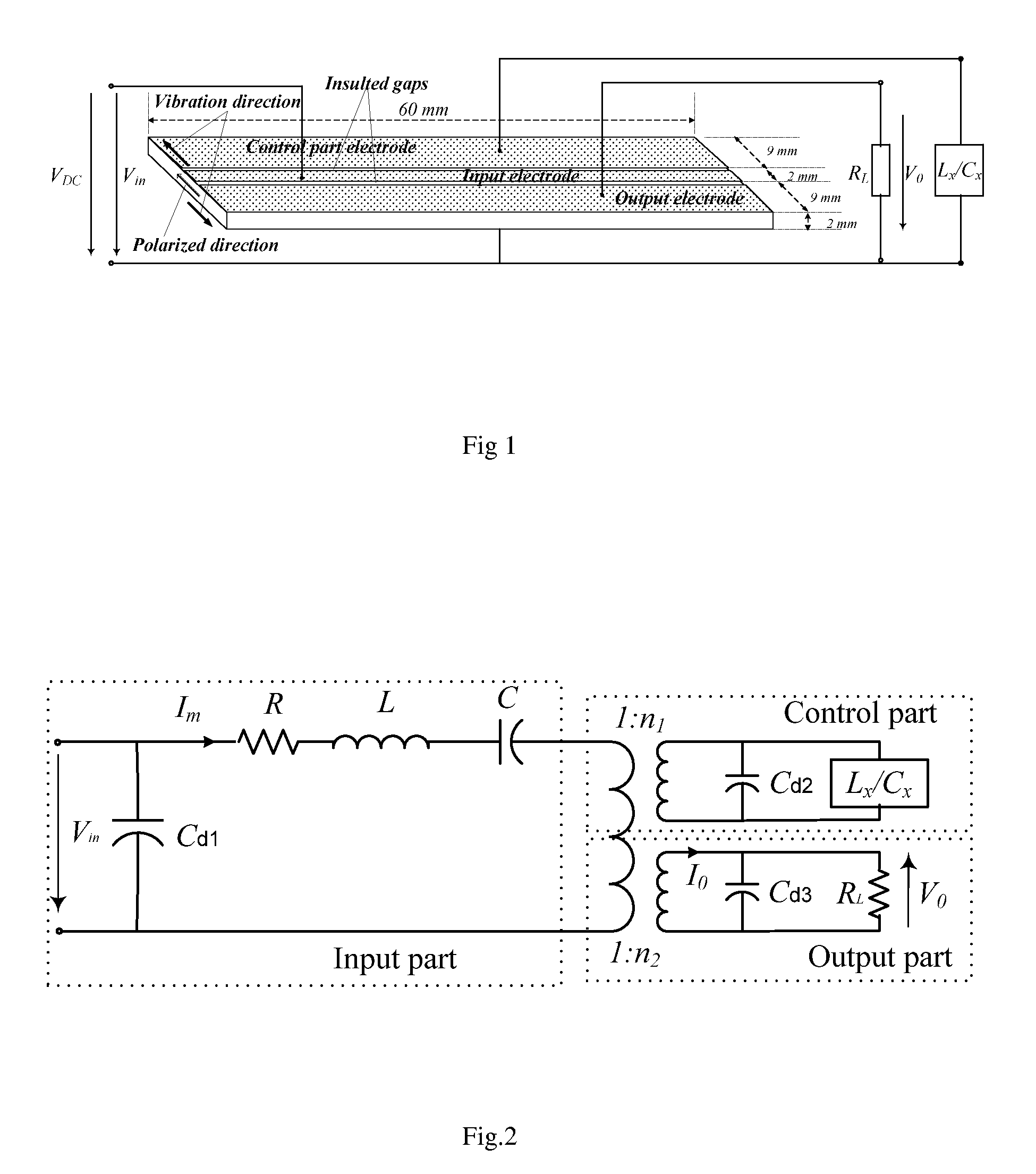
[0013]As shown in FIG. 1, it illustrates construction and dimensions of an embodiment of the piezoelectric phase shifter. The piezoelectric phase shifter comprises an input part for inputting input voltages Vin; an output part for outputting output voltages Vo; and a control part for tuning phase difference between the output and input voltages, which are made of a piezoelectric ceramic plate. Namely the piezoelectric phase shifter is made of a piezoelectric ceramic plate poled along the width direction, the polarized direction is shown in the FIG. 1. Here the input voltages Vin is Direct Current voltage inputting, and the output voltages Vo is obtained from the resistance RL.

[0014]A...


PUM


Abstract

The disclosed is a piezoelectric phase shifter, which comprises: an input part for inputting input voltages; an output part for outputting output voltages; and a control part for tuning phase difference between the output and input voltages, which are made of a piezoelectric ceramic plate. Further, the input, output and control parts are separated by insulting gaps respectively. The wide phase shift range and good ability to manage high power and relatively high energy transmission efficiency may be obtained by the disclosure.

Description

TECHNICAL FIELD OF THE INVENTION[0001]The present invention generally relates to the field of the phase shifter in electronics, and more particularly to a piezoelectric phase shifter made of a piezoelectric ceramic plate.BACKGROUND OF THE INVENTION[0002]At present, Phase shifter has many applications in sensor and actuator system, and some other AC power system. So far, the electronic and photonic phase shifters have been widely used to shift the phase of an AC voltage.[0003]The poor power management ability is the main disadvantage of those phase shifters. Ferroelectric film phase shifters based on the dielectric permittivity ∈(E) control were also developed. The disadvantages of this type of phase shifter are that it has a narrow phase shift range, and demands a relatively high DC voltage and complicated fabrication process. Nobody use piezoelectric ceramic as a phase shifter before this invention.[0004]As a result, the existing approaches do not well consider a wide phase shift r...

Claims


Application Information

Patent Timeline
IPC IPC(8): H01L41/047
CPCH03H9/66
Inventor DU, JINLONGWU, BIN
Owner NEWLIGHTING ELECTRONICS
Learn More