Novel vehicle-mounted natural gas supply system and stable gas supply method thereof
A technology of gas supply system and natural gas, which is applied in the direction of charging system, oil supply device, combustion engine, etc., can solve the problems of waste of resources and the inability of economical valves to reduce the pressure in the bottle, so as to save energy, save resources, reduce The effect of energy waste
- Summary
- Abstract
- Description
- Claims
- Application Information
AI Technical Summary
Problems solved by technology
Method used
Image
Examples
Embodiment 1
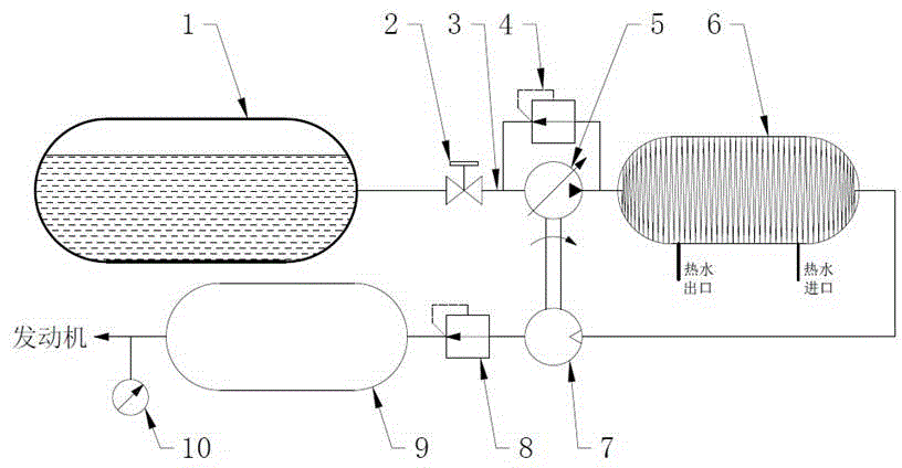
[0031] Such as figure 2As shown, a new type of vehicle-mounted natural gas supply system includes an LNG gas storage tank 1, a vaporizer 6, a liquid outlet pipe 3 connected between the LNG gas storage tank 1 and the vaporizer 6, and is used for extracting from the LNG gas storage tank 1. The LNG pump 5 for liquefied natural gas and the pneumatic driving device 7 that drives the LNG pump 5 to work; the LNG pump 5 is arranged on the liquid outlet pipe 3; the pneumatic driving device 7 is arranged on the pipeline downstream of the carburetor 6, and the The pipeline is driven by the gas pressure of natural gas, and is connected with the LNG pump 5 through the driving pipeline. In this embodiment, the pneumatic driving device 7 uses an air motor, such as but not limited to a vane air motor, a piston air motor, or a film air motor.
[0032] The working principle in this embodiment is:
[0033] In this embodiment, the self-pressurization system of the existing vehicle-mounted natu...
Embodiment 2
[0036] On the basis of Embodiment 1, a new vehicle-mounted natural gas supply system in this embodiment further includes an overflow circuit arranged in parallel at both ends of the LNG pump 5 , and an overflow valve 4 is provided on the overflow circuit.
[0037] In this embodiment, an overflow circuit is provided between the vaporizer 6 and the LNG storage tank 1 to further adjust the pressure balance. When the pressure in the vaporizer 6 is higher than the set value, the LNG pump 5 stops working, the overflow valve 4 will open, and part of the gasified natural gas in the vaporizer 6 will return to the storage tank through the overflow valve 4 through the liquid outlet pipe 3. In the liquid phase space in the gas tank 1, when the pressure in the carburetor 6 is reduced and balanced, the overflow valve 4 is closed, and the LNG pump 5 continues to work, so that the self-balancing effect of the system is better.
Embodiment 3
[0039] On the basis of Embodiment 2, in this embodiment, the downstream of the carburetor 6 is also connected with a pressure reducing valve 8 and a buffer tank 9 in sequence, and a fuel shutoff valve 2 is also arranged on the outlet pipe 3, and the downstream of the buffer tank 9 is connected to The pipeline on the engine is also provided with a pressure gauge 10 . The natural gas vaporized by the carburetor 6 passes through the pneumatic driving device 7 and then enters the pressure reducing and regulating valve 8 for decompression, and finally supplies the engine through the buffer tank 9 for use. A gas flow measurement device (such as a flow meter) may be further provided on the pneumatic driving device 7 for real-time monitoring of gas supply and real-time detection of gas consumption.
[0040] The LNG pump 5 and overflow valve 4 are located between the fuel cutoff valve 2 and the carburetor 6 . The pneumatic driving device 7 is arranged on the pipeline between the carbu...
PUM
 Abstract
Description
Claims
Application Information
 - R&D
- Intellectual Property
- Life Sciences
- Materials
- Tech Scout
- Unparalleled Data Quality
- Higher Quality Content
- 60% Fewer Hallucinations
Browse by: Latest US Patents, China's latest patents, Technical Efficacy Thesaurus, Application Domain, Technology Topic, Popular Technical Reports.
© 2025 PatSnap. All rights reserved.Legal|Privacy policy|Modern Slavery Act Transparency Statement|Sitemap|About US| Contact US: help@patsnap.com


