

Fuel cell
- Summary
- Abstract
- Description
- Claims
- Application Information
AI Technical Summary
Benefits of technology
Problems solved by technology
Method used
Image

Examples
first embodiment
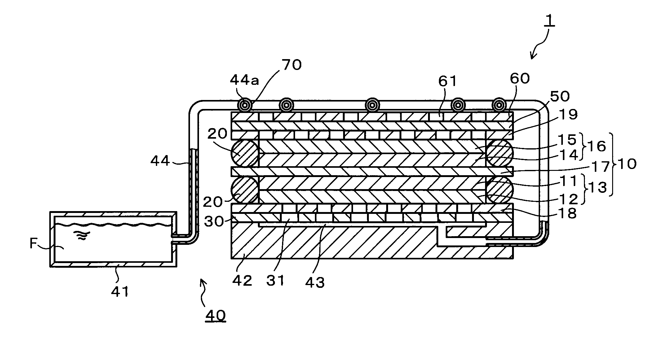
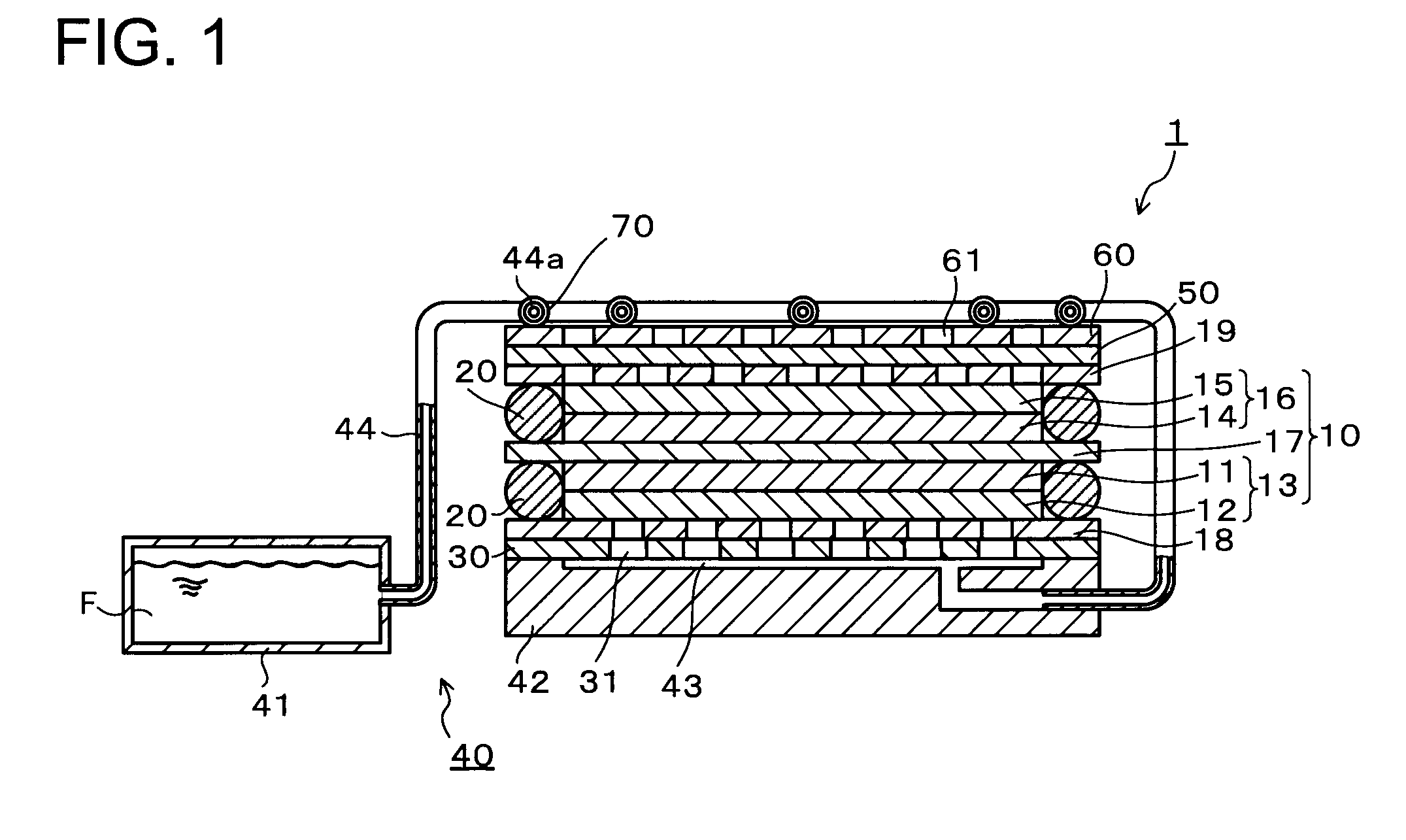
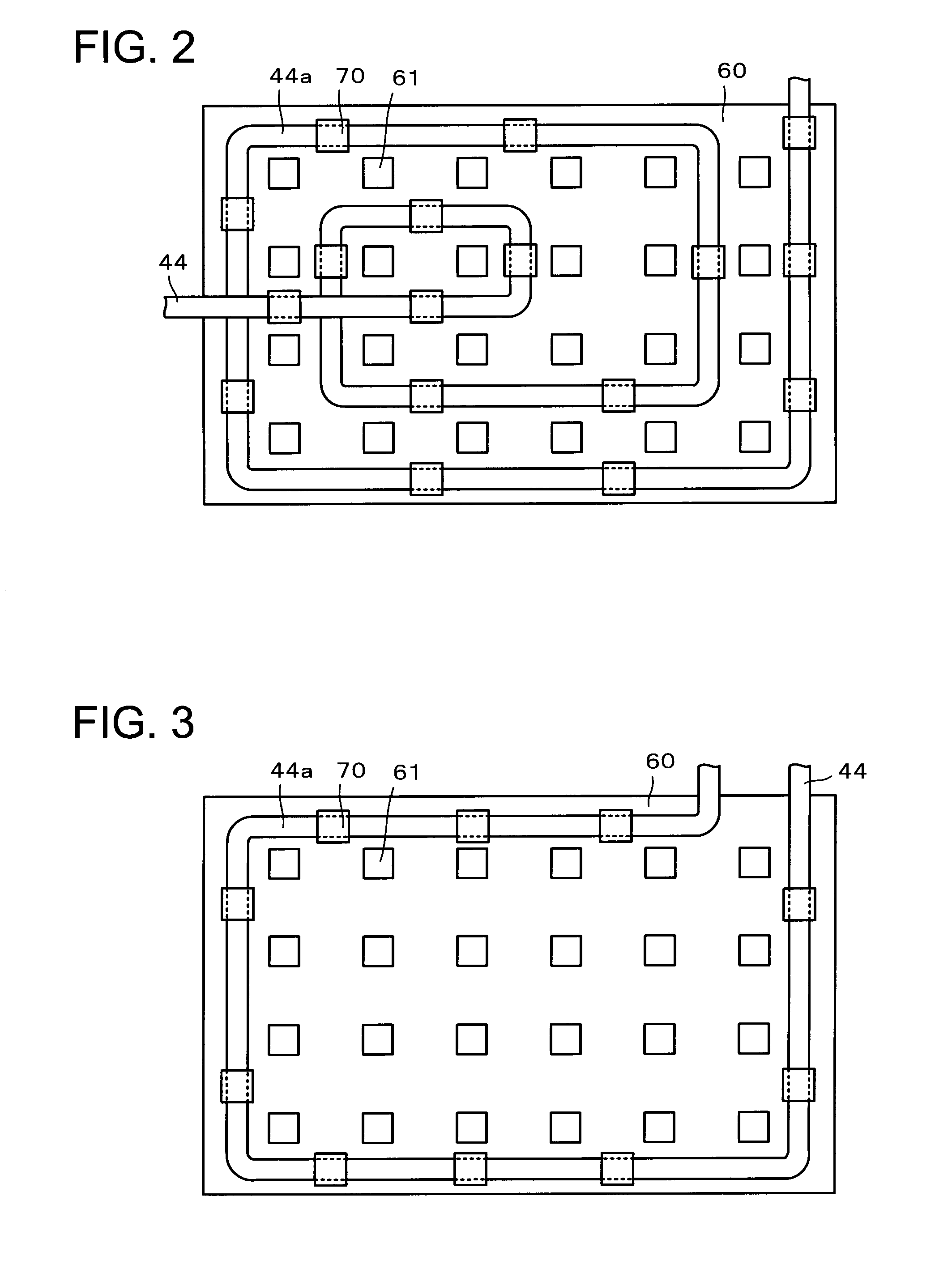
[0028]FIG. 1 is a cross-sectional view showing the structure of a fuel cell 1 of a first embodiment according to the present invention. FIG. 2 is a plane view showing the structure of a surface cover 60 when the surface cover 60 is seen from above the fuel cell 1 in FIG. 1, that is, from the outside of the fuel cell 1. FIG. 3 is a plane view showing another layout example of a heating part 44a of a channel 44. FIG. 4 is a cross-sectional view showing another structure of the channel 44 in the fuel cell 1 of the first embodiment according to the present invention. FIG. 5 is a cross-sectional view showing still another structure of the channel 44 in the fuel cell 1 of the first embodiment according to the present invention. FIG. 6 is a cross-sectional view showing the structure when the fuel cell 1 of the first embodiment according to the present invention includes a pump 85.
[0029]As shown in FIG. 1, the fuel cell 1 has: a fuel cell unit 10 constituting an electromotive part; an anode...
second embodiment
[0064]FIG. 7 is a cross-sectional view showing the structure of a fuel cell 1 of a second embodiment according to the present invention. FIG. 8 is a plane view showing the structure when the fuel cell 1 in FIG. 7 is seen from above the fuel cell 1. The same components as those of the fuel cell 1 of the first embodiment will be denoted by the same reference numerals and symbols and redundant description thereof will be simplified.
[0065]As shown in FIG. 7, the fuel cell 1 includes: a fuel cell unit 10 constituting an electromotive part; an anode conductive layer 18 and a cathode conductive layer 19 provided on an anode (fuel electrode) side and a cathode (air electrode) side of the fuel cell unit 10 respectively; a fuel distribution layer 30 disposed to face the anode conductive layer 18 and having a plurality of openings 31; a fuel supply part 43 disposed opposite the fuel cell unit 10 across the fuel distribution layer 30 to supply a liquid fuel F to the fuel distribution layer 30; ...
example 1
[0074]A fuel cell used in the example 1 will be described with reference to FIG. 6 since it includes the same structure as that of the fuel cell 1 shown in FIG. 6.
[0075]First, a method of fabricating a fuel cell unit 10 will be described.
[0076]A perfluorocarbon sulfonic acid solution as proton conductive resin, and water and methoxypropanol as dispersion mediums were added to carbon black carrying anode catalyst particles (Pt:Ru=1:1), and the carbon black carrying the anode catalyst particles were dispersed, whereby paste was prepared. The obtained paste was applied on porous carbon paper (40 mm×30 mm rectangle) being an anode gas diffusion layer 12, whereby an anode catalyst layer 11 with a 100 μm thickness was obtained.
[0077]A perfluorocarbon sulfonic acid solution as proton conductive resin, and water and methoxypropanol as dispersion mediums were added to carbon black carrying cathode catalyst particles (Pt), and the carbon black carrying the cathode catalyst particles were disp...
PUM
 Abstract
Description
Claims
Application Information