Head mount display

Active Publication Date: 2010-06-24
BROTHER KOGYO KK
View PDF6 Cites 55 Cited by
  • Summary
  • Abstract
  • Description
  • Claims
  • Application Information

AI Technical Summary

Benefits of technology

[0012]The present invention has been made under such circumstances, and it is an object of the present invention to provide a head mount

Problems solved by technology

This positional displacement would lead to erroneous inputting.
Due to such movement of the key, the user would operate an operation key different from a desired operation key

Method used


Image

  • Head mount display
  • Head mount display
  • Head mount display

Examples


Embodiment Construction

[0032]A head mount display (also referred to as “HMD” hereinafter) 1 according to one embodiment of the present invention is explained specifically in conjunction with drawings.

[Overall Constitution of HMD]

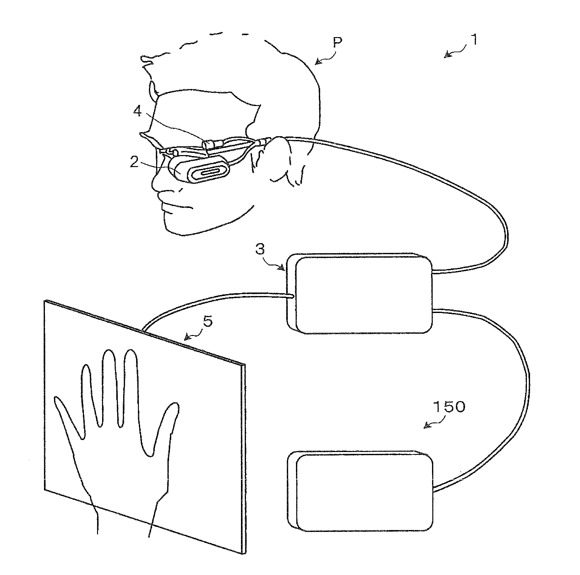
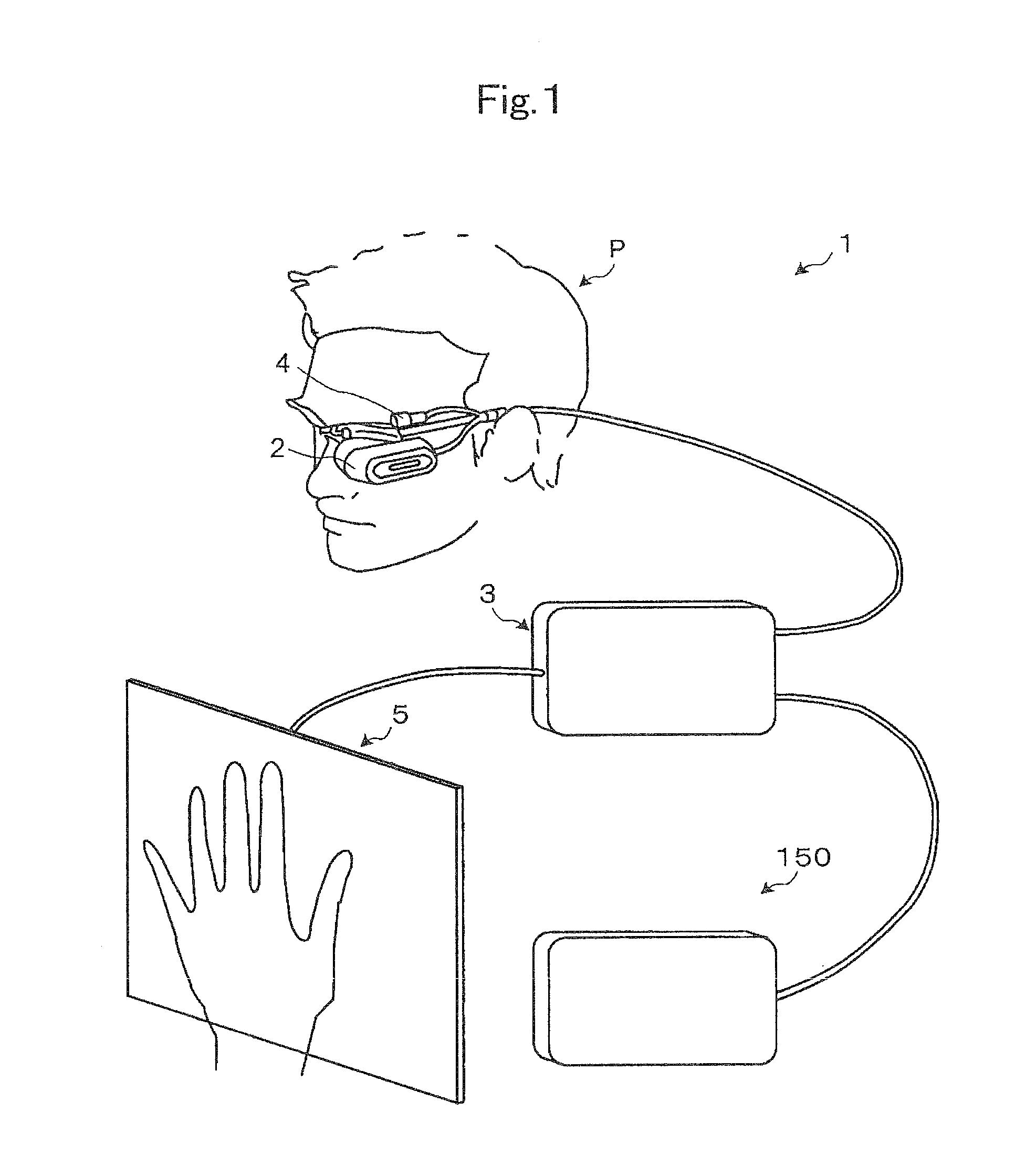
[0033]As shown in FIG. 1, the HMD 1 according to this embodiment includes an HMD body 2 which a user P mounts on his head, a controller 3, a CCD (Charge Coupled Device) camera 4, touch panel 5 which detects a contact of a finger of the user P therewith, and a control box 150 which is communicably connected with the controller 3.

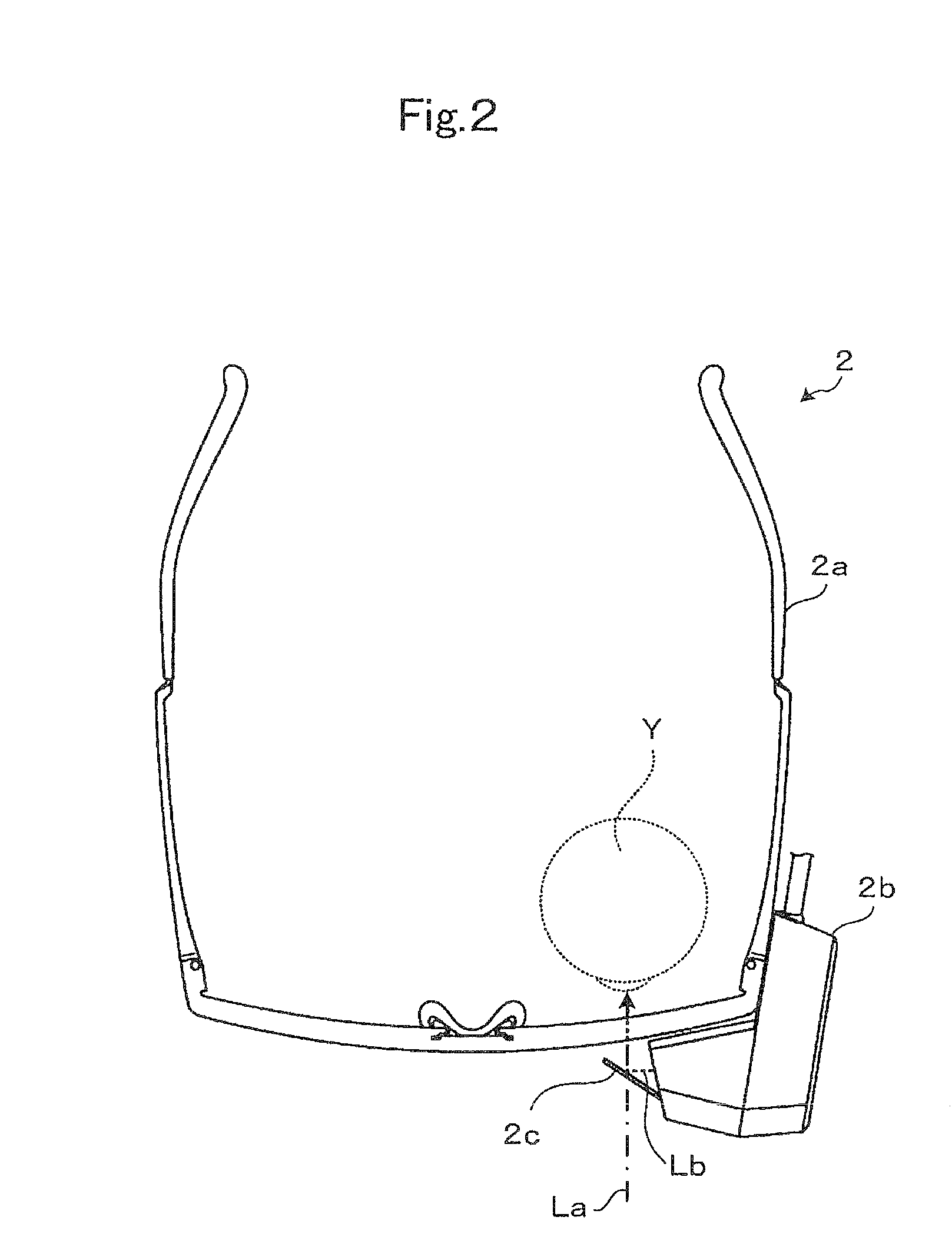
[0034]The HMD body 2 performs a display which allows the user P to observe various content data such as moving image files, still image files and document files and a virtual operation panel as images in a state that the user P mounts the HMD body 2 on his head. The HMD body 2 is a retinal scanning display which allows the user P to observe an image corresponding to content data (hereinafter simply referred to as “content”) by scanning light whose intensity...


PUM


Abstract

A HMD photographs at least a portion of a field of view of a user, and detects a hand of the user based on a result of analysis of an imaged image. The HMD performs a control of deciding and displaying a position of an operation part of a virtual operation panel based on a position of the detected hand of the user. A position associated with the hand visible to the user is set as a display position of the virtual operation panel which tracks the position of the hand of the user. The HMD determines whether or not the virtual operation panel is operated based on a contact position of a finger of the user detected by a touch panel, and performs a control corresponding to an operation position of the virtual operation panel when it is determined that the virtual operation panel is operated.

Description

CROSS-REFERENCE TO RELATED APPLICATIONS[0001]This application is based on and claims the benefit of priority from Japanese Patent Application No. 2008-324646 filed on Dec. 19, 2008, the entire contents of which are incorporated herein by reference.BACKGROUND[0002]1. Field[0003]The present invention relates to a head mount display. The present invention relates more particularly to a see-through type head mount display provided with a display unit which allows transmission of an ambient light therethrough and projects an image light corresponding to image data to an eye of a user thus allowing the user to observe an image corresponding to the image light.[0004]2. Description of the Related Art[0005]Conventionally, there has been known an information processing device which includes a memory unit for storing various content data such as moving image files, still image files and document files, and a reproducing unit which reproduces the content data stored in the memory unit.[0006]A t...

Claims


Application Information

Patent Timeline
IPC IPC(8): G09G5/00G06F3/041
CPCG01S5/16G02B27/017G02B2027/0138G02B2027/014G06F3/04886G06F3/011G06F3/0304G06F3/042G06F3/0426G02B2027/0187
Inventor KATAYAMA, SHINGO
Owner BROTHER KOGYO KK
Why Eureka
Try Eureka