Ink-Jet Recording Method and Ink-Jet Recording Apparatus

a recording method and ink jet technology, applied in the field of inkjet recording methods and ink jet recording apparatuses, can solve the problems of increased cost, insufficient bleeding prevention effect, deterioration of color image recording quality, etc., and achieve excellent recording quality of recorded matter, effective prevention of bleeding, and low cost

Active Publication Date: 2010-06-24
BROTHER KOGYO KK
View PDF5 Cites 2 Cited by
  • Summary
  • Abstract
  • Description
  • Claims
  • Application Information

AI Technical Summary

Benefits of technology

[0007]In view of the above, an object of the present invention is to provide an ink-jet recording method and an ink-jet recording apparatus in whi

Problems solved by technology

If the bleeding is caused as described above, the recording quality of the color image is deteriorated.
However, the techniques described above involve the following problems.
Firstly, the technique in which the ink to be used for the boundary portion is selected based on the permeability involves such a problem that the bleeding-preventive effect is insufficient.
Secondly, in the technique in which the reactive color ink is used and in the technique which uses the liquid to improve the printing performance, it is necessary that the reactive color ink

Method used


Image

  • Ink-Jet Recording Method and Ink-Jet Recording Apparatus
  • Ink-Jet Recording Method and Ink-Jet Recording Apparatus
  • Ink-Jet Recording Method and Ink-Jet Recording Apparatus

Examples


first embodiment

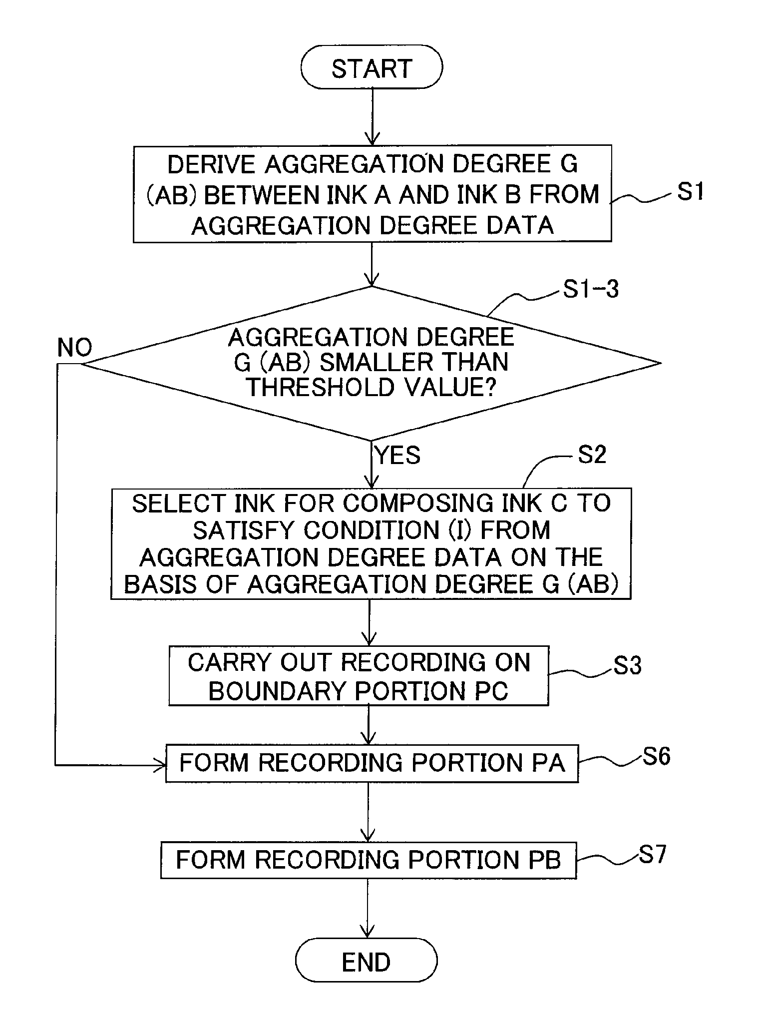
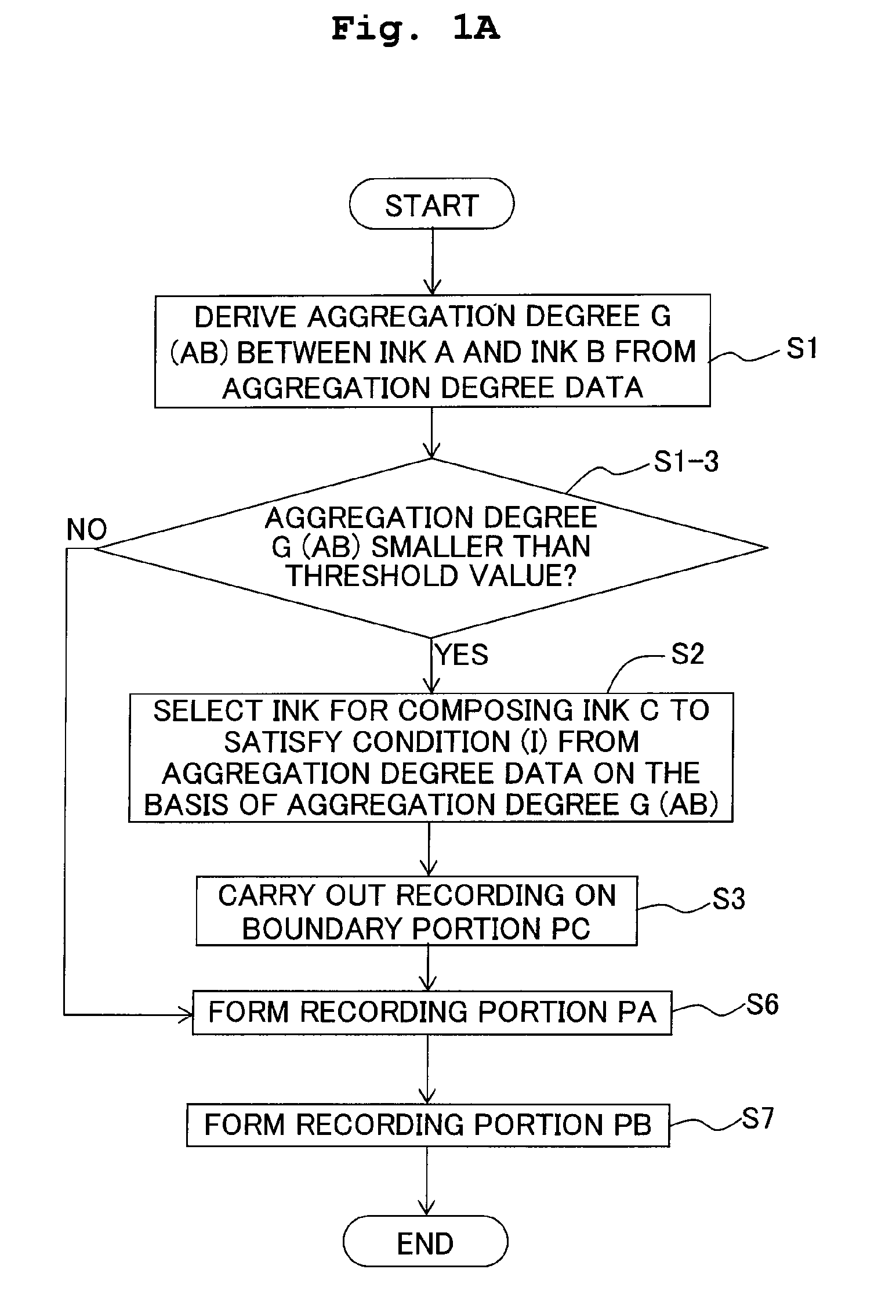
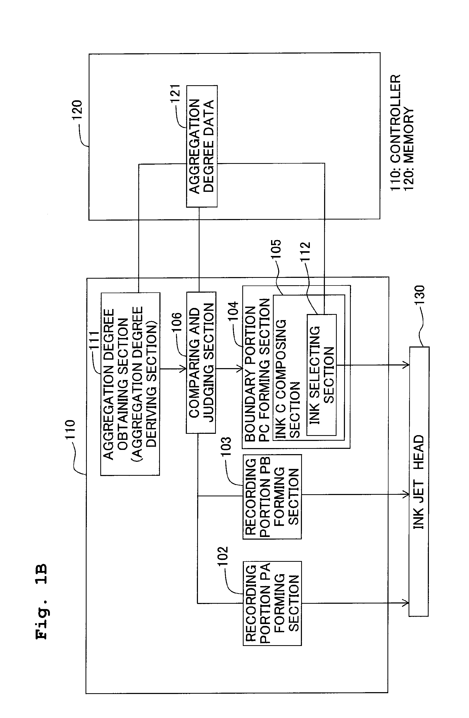
[0084]The block diagram shown in FIG. 1B illustrates the relationship among the controller, the memory, and the ink jet head in an ink-jet recording apparatus of this embodiment. As shown in FIG. 1B, the aggregation degree data 121 is stored in the memory 120. The controller 110 includes the aggregation degree obtaining section (aggregation degree deriving section) 111, the comparing and judging section 106, the recording portion PA forming section 102, the recording portion PB forming section 103, and the boundary portion PC forming section 104. Further, the boundary portion PC forming section 104 includes the ink C composing section 105, and the ink C composing section 105 includes the ink selecting section 112. The aggregation degree deriving section 111 and the ink selecting section 112 are connected to the aggregation degree data 121. The ink jet recording apparatus of this embodiment may further include the recording-related information obtaining mechanism (not shown). For exa...

second embodiment

[0100]The block diagram shown in FIG. 2B illustrates the relationship among the controller, the memory, and the ink jet head in an ink-jet recording apparatus of this embodiment. As shown in FIG. 2B, the aggregation degree data 121 and the lightness data 122 are stored in the memory 120. The controller 110 includes the aggregation degree obtaining section (aggregation degree deriving section) 111, the comparing and judging section 106, the recording portion PA forming section 102, the recording portion PB forming section 103, and the boundary portion PC forming section 104. Further, the boundary portion PC forming section 104 includes the ink C composing section 105, and the ink C composing section 105 includes the ink selecting section 112, the lightness deriving section 113, and the lightness selecting section 114. The aggregation degree deriving section 111, the ink selecting section 112, and the lightness selecting section 114 are connected to the aggregation degree data 121. Th...

third embodiment

[0117]The block diagram shown in FIG. 3c illustrates the relationship among the controller, the memory, and the ink jet head in an ink-jet recording apparatus of this embodiment. As shown in FIG. 3c, the aggregation degree data 121 and the hue data 123 are stored in the memory 120. The controller 110 includes the aggregation degree obtaining section (aggregation degree deriving section) 111, the comparing and judging section 106, the recording portion PA forming section 102, the recording portion PB forming section 103, and the boundary portion PC forming section 104. Further, the boundary portion PC forming section 104 includes the ink C composing section 105, and the ink C composing section 105 includes the ink selecting section 112, the lightness deriving section 113, the lightness selecting section 114, the color difference deriving section 115, and the color difference selecting section 116. The lightness data 122 is included in the hue data 123. The aggregation degree deriving...


PUM

PropertyMeasurementUnit
Magnetic fieldaaaaaaaaaa
Volumeaaaaaaaaaa
Angleaaaaaaaaaa

Abstract

An ink-jet recording method includes: determining an aggregation degree G (AB) brought about when the ink A and the ink B are brought in contact with each other, at least one of the ink A and the ink B containing a pigment; judging, based on the aggregation degree G (AB), whether or not a boundary portion PC is to be formed at a boundary between a recording portion PA of the ink A and a recording portion PB of the ink B by using an ink C; forming the recording portion PA; forming the recording portion PB; and forming the boundary portion PC if it is judged that the boundary portion PC is to be formed. In the ink jet recording method, the cost is low, the recording quality of a recorded matter is excellent, and the bleeding can be effectively avoided.

Description

CROSS REFERENCE TO RELATED APPLICATION[0001]The present application claims priority from Japanese Patent Application No. 2008-328717, filed on Dec. 24, 2008, the disclosure of which is incorporated herein by reference in its entirety.BACKGROUND OF THE INVENTION[0002]1. Field of the Invention[0003]The present invention relates to an ink-jet recording method and an ink jet recording apparatus.[0004]2. Description of the Related Art[0005]When the ink jet recording is performed, a phenomenon so-called bleeding, in which the ink is blurred, is caused in some cases at the boundary portion between areas having different color schemes. If the bleeding is caused as described above, the recording quality of the color image is deteriorated. Those having been hitherto suggested in order to suppress the bleeding include, for example, a technique in which an ink to be used for the boundary portion is selected based on the penetrating performance or permeability (Japanese Patent Application Laid-o...

Claims


Application Information

Patent Timeline
IPC IPC(8): B41J29/38B41J2/01B41J2/175B41J2/21B41M5/00C09D11/00C09D11/322C09D11/326C09D11/328C09D11/38C09D11/40
CPCG06K2215/0094G06K15/102
Inventor HAYASHIDA, KENTA
Owner BROTHER KOGYO KK
Why Eureka
Try Eureka