Holographic Substrate-Guided Wave-Based See-Through Display

a technology of see-through display and substrate, applied in the direction of holographic processes, instruments, optical elements, etc., can solve the problems of limiting the application of users, dim view of the outside world, and users' inability to see through to the real world, so as to increase the viewing area or the quality of the total display

Active Publication Date: 2010-06-24
LUMINIT
View PDF7 Cites 170 Cited by
  • Summary
  • Abstract
  • Description
  • Claims
  • Application Information

AI Technical Summary

Benefits of technology

[0013]Another aspect of the invention can have a second microdisplay, capable of emitting light in the form of an image. This second microdisplay can send its output to a second holographic lens, capable of accepting the light in the form of an image from the microdisplay, and capable of transmitting the accepted light in the form of an image. This second holographic lens can send its output to the elongate transparent substrate, capable of accepting the light in the form of an image from the second holographic lens at a third location, and transmitting the light in the form of an image along a length of the substrate by total internal reflection to the second location, the elongate substrate being capable of transmitting the accepted light in the form of an image at the second location. The transparent holographic grating, capable of accepting the light transmitted by the elongate substrate from the second holographic lens and transmitting it to the location outside of the holographic grating as a viewable image. Advantageously, the two microdisplays can send partial images in cooperation to increase the viewing area or quality of the total display.

Problems solved by technology

But none of them has allowed users to see through to the real world, severely limiting possible applications.
These partially-see-through head-mounted displays suffer from poor light transmission through the combiner resulting in a dim view of the outside world and decreased virtual image brightness.
But the image quality was poor, mostly because of the color dispersion created by a single hologram for a broad-band source.
They used either a single laser source for LCD illumination thus not enabling the color imagery or proposed very complicated hologram recording geometries for generating aspheric recording wave-fronts which are rather complicated and costly to be implemented in practice.
While providing a see-through capability, such an approach suffers from stray light generated by unwanted diffraction into undesired diffractive orders that substantially decreases the image quality and contrast.
While creating a see-through imagery, fabrication of such elements in mass quantities can be prohibitively expensive.

Method used


Image

  • Holographic Substrate-Guided Wave-Based See-Through Display
  • Holographic Substrate-Guided Wave-Based See-Through Display
  • Holographic Substrate-Guided Wave-Based See-Through Display

Examples


Embodiment Construction

[0048]Although the present invention is susceptible of embodiment in various forms, there is shown in the drawings and will hereinafter be described presently preferred embodiments with the understanding that the present disclosure is to be considered an exemplification of the invention and is not intended to limit the invention to the specific embodiments illustrated.

[0049]It is to be further understood that the title of this section of the specification, namely, “Detailed Description of the Invention” relates to a rule of the United States Patent and Trademark Office, and is not intended to, does not imply, nor should be inferred to limit the subject matter disclosed herein or the scope of the invention.

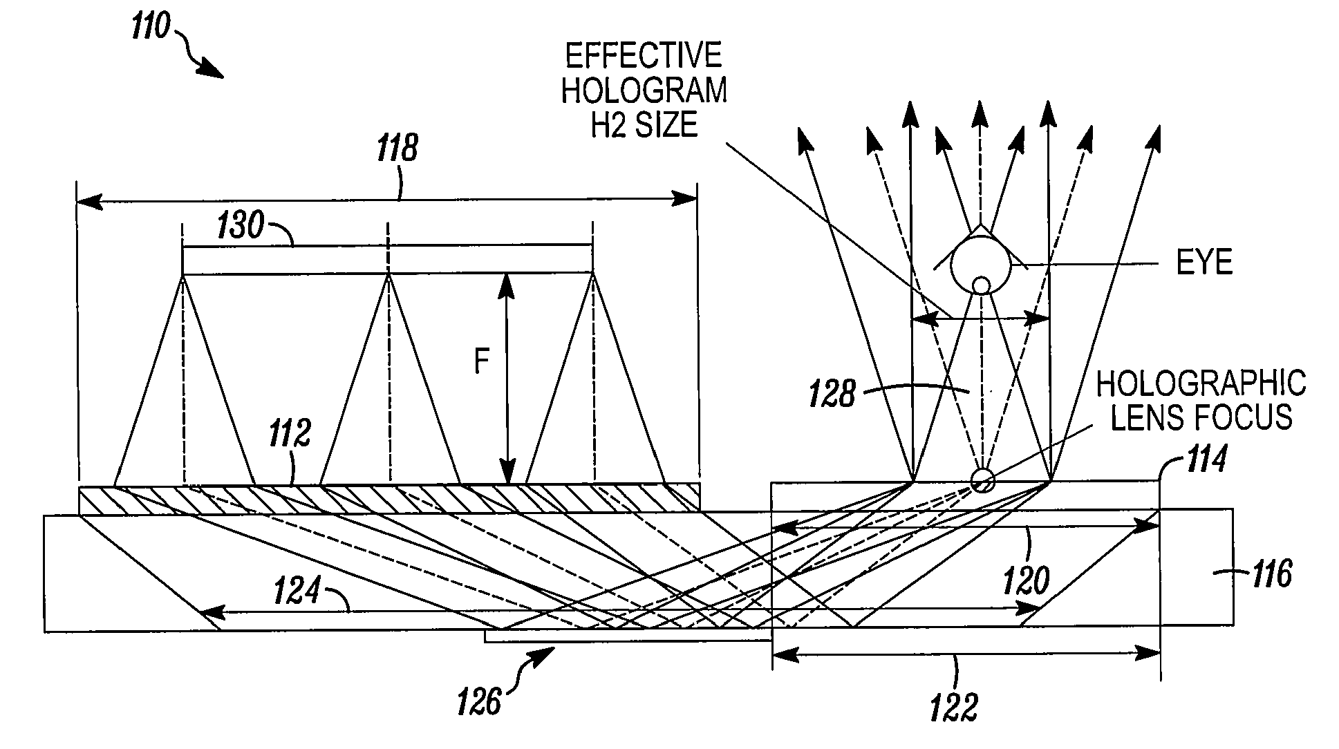
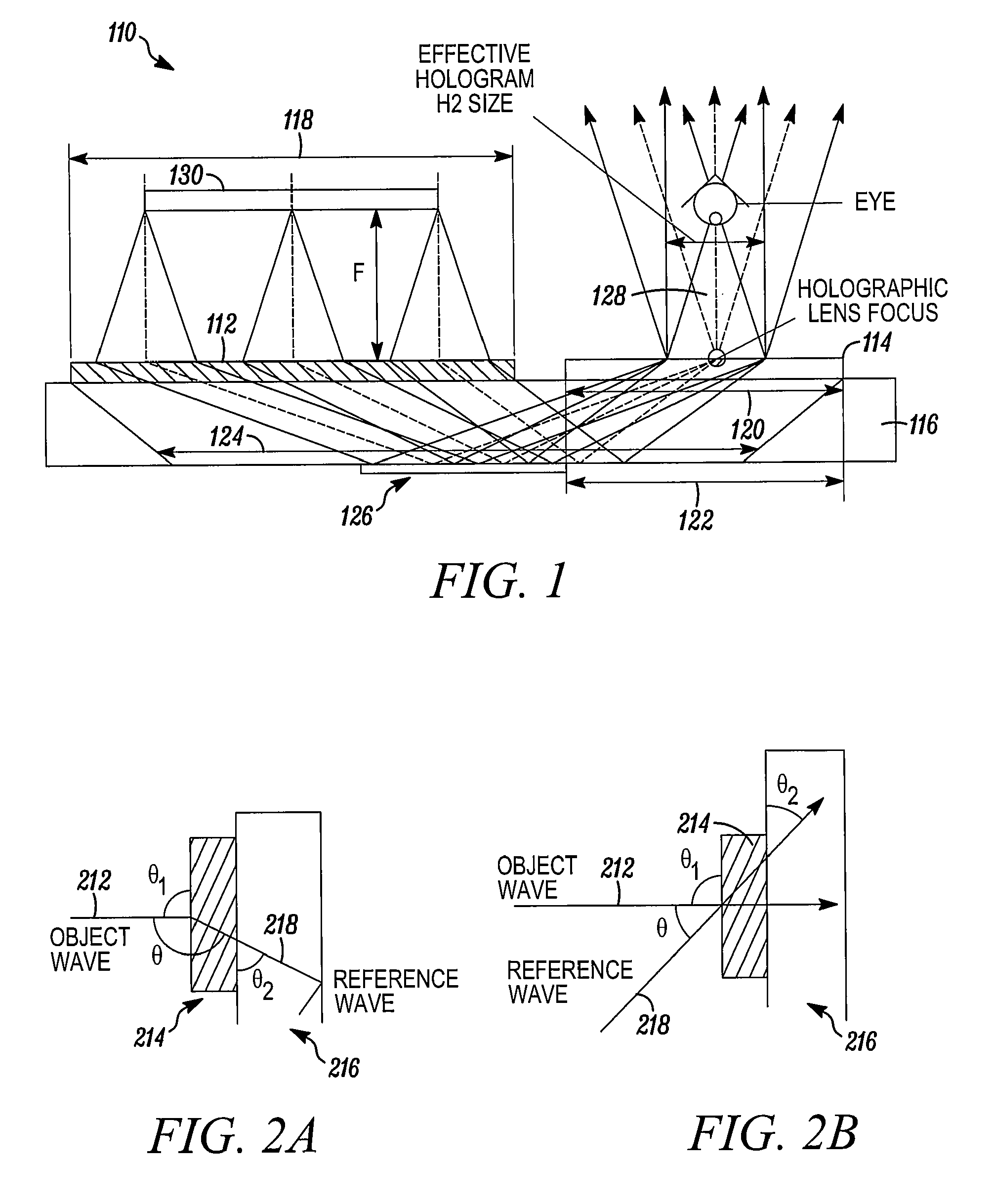
[0050]What follows is a successful design for head-mounted display based on Substrate-Guided Wave (SGW) holograms, with the optical parameters comparable to head-mounted display based on common optics, with performance in terms of see-through capability, brightness, weight, and cos...


PUM


Abstract

A holographic substrate-guided wave-based see-through display can has a microdisplay, capable of emitting light in the form of an image. The microdisplay directs its output to a holographic lens, capable of accepting the light in the form of an image from the microdisplay, and capable of transmitting the accepted light in the form of an image. The holographic lens couples its output to an elongate transparent substrate, capable of accepting the light in the form of an image from the holographic lens at a first location, and transmitting the light in the form of an image along a length of the substrate by total internal reflection to a second location spaced from the first location, the elongate substrate being capable of transmitting the accepted light in the form of an image at the second location. The substrate couples out what it receives to a transparent holographic grating, capable of accepting the light transmitted from the elongate substrate and transmitting it to a location outside of the holographic grating as a viewable image.

Description

BACKGROUND OF THE INVENTION[0001]Head-mounted and head-up displays for simulation, training, entertainment, and military applications have been in use for a number of years. They have a great potential for construction work, sports, space suit, medicine, education, mobile communications and for other fields. Substantial efforts are made to reduce size, weight, cost, and the number of optical and electronic elements of a display. Further efforts are made to improve brightness, contrast, and image quality.[0002]A head-mounted display (HMD) can use a micro-display source such as a liquid crystal display (LCD) or liquid crystal on silicon (LCOS) with a backlight. An alternative is to use an organic light-emitting diode (OLED) display, reflective and / or refractive optics to create a magnified virtual image of the micro-display source for a viewer's eye(s). A number of opaque head-mounted displays have been developed.[0003]But none of them has allowed users to see through to the real worl...

Claims


Application Information

Patent Timeline
Patent Type & Authority Applications(United States)
IPC IPC(8): G03H1/04G02B5/32G03H1/22
CPCG02B5/188G02B5/32G02B6/00G02B6/34G02B27/0172G03H2270/21G03H1/0408G03H2001/0439G03H2001/261G03H2210/63G02B2027/0174
Inventor DIMOV, FEDORAYE, TINYU, KEVINSOBOLEVA, SVETLANAYIN, KHIN SWEKYAW, MYOVOLOSCHENKO, DMITRY
Owner LUMINIT
Why Eureka
Try Eureka