Pointless illumination device

Inactive Publication Date: 2010-06-24
BRIGHT VIEW ELECTRONICS
View PDF1 Cites 6 Cited by
  • Summary
  • Abstract
  • Description
  • Claims
  • Application Information

AI Technical Summary

Benefits of technology

[0006]In view of the description above, an objective of the present invention is to provide

Problems solved by technology

However the flashing of the fluorescent lamp due to AC power may make users' eyes feel uncomfortable.
Besides, the fluorescent lamp consumes a lot of power and has a poison fluorescent powder coated on the lamp wall so it does not comply with the demands of environmental protection.
However,

Method used


Image

  • Pointless illumination device
  • Pointless illumination device
  • Pointless illumination device

Examples


Example

[0013]The present invention will now be described in more detail hereinafter with reference to the accompanying drawings that show various embodiments of the invention.

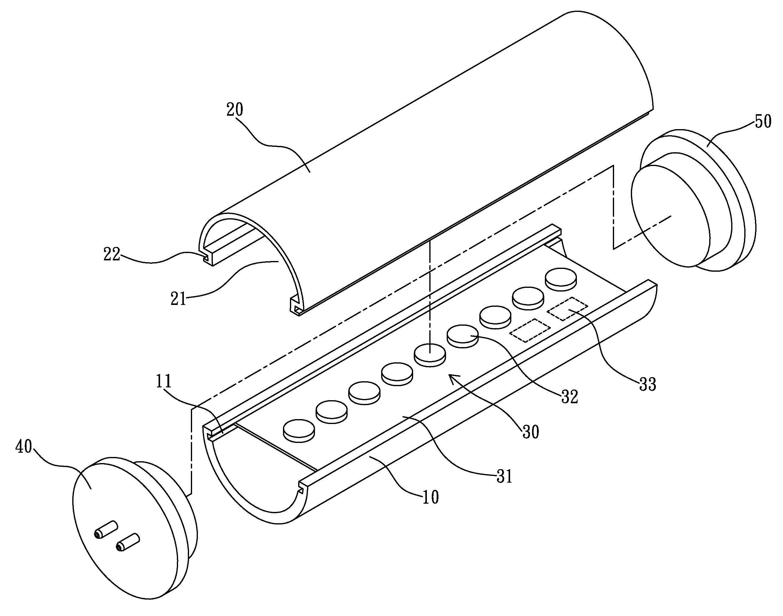
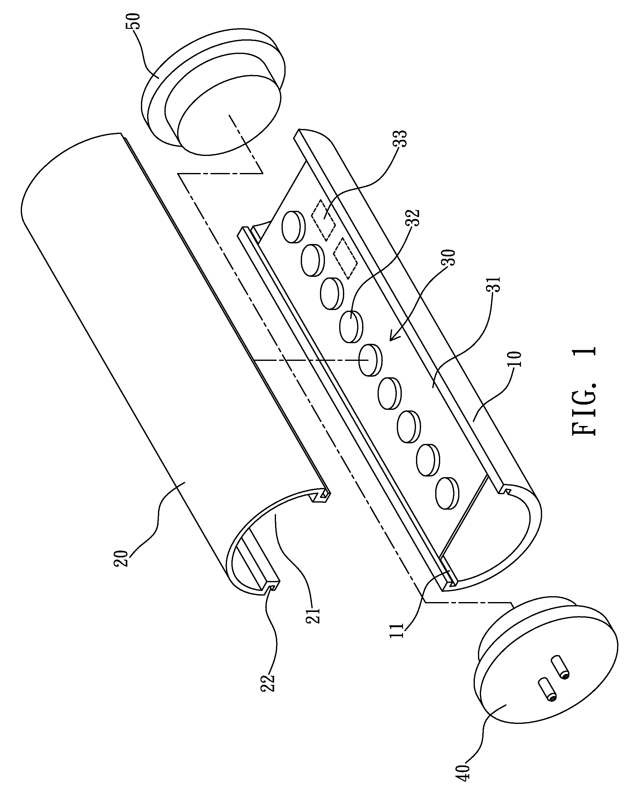
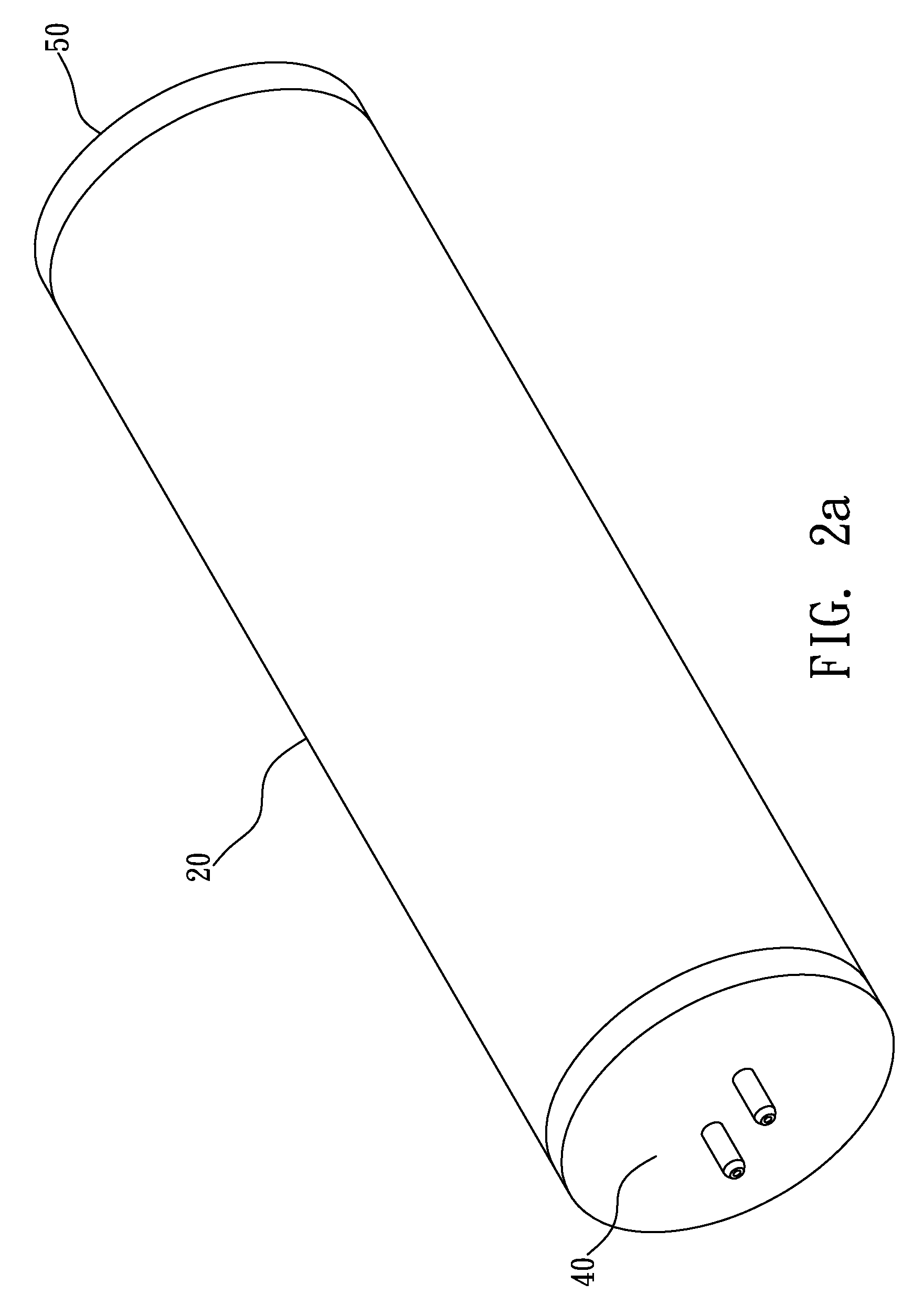
[0014]Please refer to FIG. 1˜FIG. 2(b) first. FIG. 1 shows an exploded view of a preferred embodiment of pointless illumination device of the present invention; FIG. 2(a) is an assembly schematic illustration of a preferred embodiment of a pointless illumination device of the present invention; FIG. 2(b) is a local cross section view of FIG. 2(a).

[0015]As indicated in the drawings, the present pointless illumination device includes: a body 10; a cover 20; a light source module 30; a first contact portion 40; and a second contact portion 50.

[0016]In this device, the body 10 has an approximately semicircle cross section and is made of a light transparent material, for example but not limited to glass or plastic, and has two approximately parallel grooves 11 at two sides.

[0017]The cover 20 is capable of mating with the b...


PUM


Abstract

The present invention relates to a pointless illumination device, comprising: a body; a cover, made of a light spreading material which can uniformly spread out the light of a plurality of light emitting devices; a light source module; a first contact portion; and a second contact portion. The light emitted from the light source module is uniformly spread through the cover so that the phenomenon of pointwise illumination does not exist in the illumination device.

Description

BACKGROUND OF THE INVENTION[0001]1. Field of the Invention[0002]The present invention relates to an illumination device, especially to a pointless illumination device, having a cover capable of uniformly spreading the light of a plurality of light emitting devices so that the phenomenon of pointwise illumination does not exist in the illumination device.[0003]2. Description of the Related Art[0004]Up to now, the fluorescent lamp has long been used as illumination device for households and factories. However the flashing of the fluorescent lamp due to AC power may make users' eyes feel uncomfortable. Besides, the fluorescent lamp consumes a lot of power and has a poison fluorescent powder coated on the lamp wall so it does not comply with the demands of environmental protection.[0005]For present, there are some lamps utilizing light emitting diodes as light source to save power and comply with the demands of environmental protection. However, due to the directionality of the light em...

Claims


Application Information

Patent Timeline
IPC IPC(8): F21V21/00
CPCF21K9/00Y10S362/80
Inventor CHIANG, JUNG HWA
Owner BRIGHT VIEW ELECTRONICS
Why Eureka
Try Eureka