PTFE Fabric Articles and Method of Making Same

a technology of ptfe fabric and ptfe thread, which is applied in the field of unique ptfe fabric articles, can solve the problems of ineffective modification of bulk substrate properties, porosity and permeability, and treatment with or following amorphous locking, and achieve the effect of minimizing movement or slippage of fibers

Active Publication Date: 2010-06-24
WL GORE & ASSOC INC
View PDF15 Cites 40 Cited by
  • Summary
  • Abstract
  • Description
  • Claims
  • Application Information

AI Technical Summary

Benefits of technology

[0010]The present invention is directed to a unique PTFE fabric structure comprising a plurality of PTFE fibers overlapping at intersections, wherein at least a portion of the intersections have PTFE masses which mechanically lock the overlapping PTFE fibers. The term “PTFE” is intended to include PTFE homopolymers and PTFE-containing polymers. By “PTFE fiber” or “fibers” is meant PTFE-containing fibers, including, but not limited to, filled fibers, blends of PTFE fiber and other fiber, various composite structures, fibers with PTFE outer surfaces. As used herein, the terms “structure” and “fabric” may be used interchangeably or together to refer to constructions comprising, but not limited to, knitted PTFE fibers, woven PTFE fibers, nonwoven PTFE fibers, laid scrims of PTFE fibers, etc., and combinations thereof. The term “intersection(s)” refers to any location in a fabric whe

Problems solved by technology

Martakos et al. distinguish over conventional processes by noting that the prior art techniques operate on finished, fabricated and/or finally processed materials, which are “ineffective at modifying bulk substrate properties, such as porosity and permeabil

Method used


Image

  • PTFE Fabric Articles and Method of Making Same
  • PTFE Fabric Articles and Method of Making Same
  • PTFE Fabric Articles and Method of Making Same

Examples


example 1a

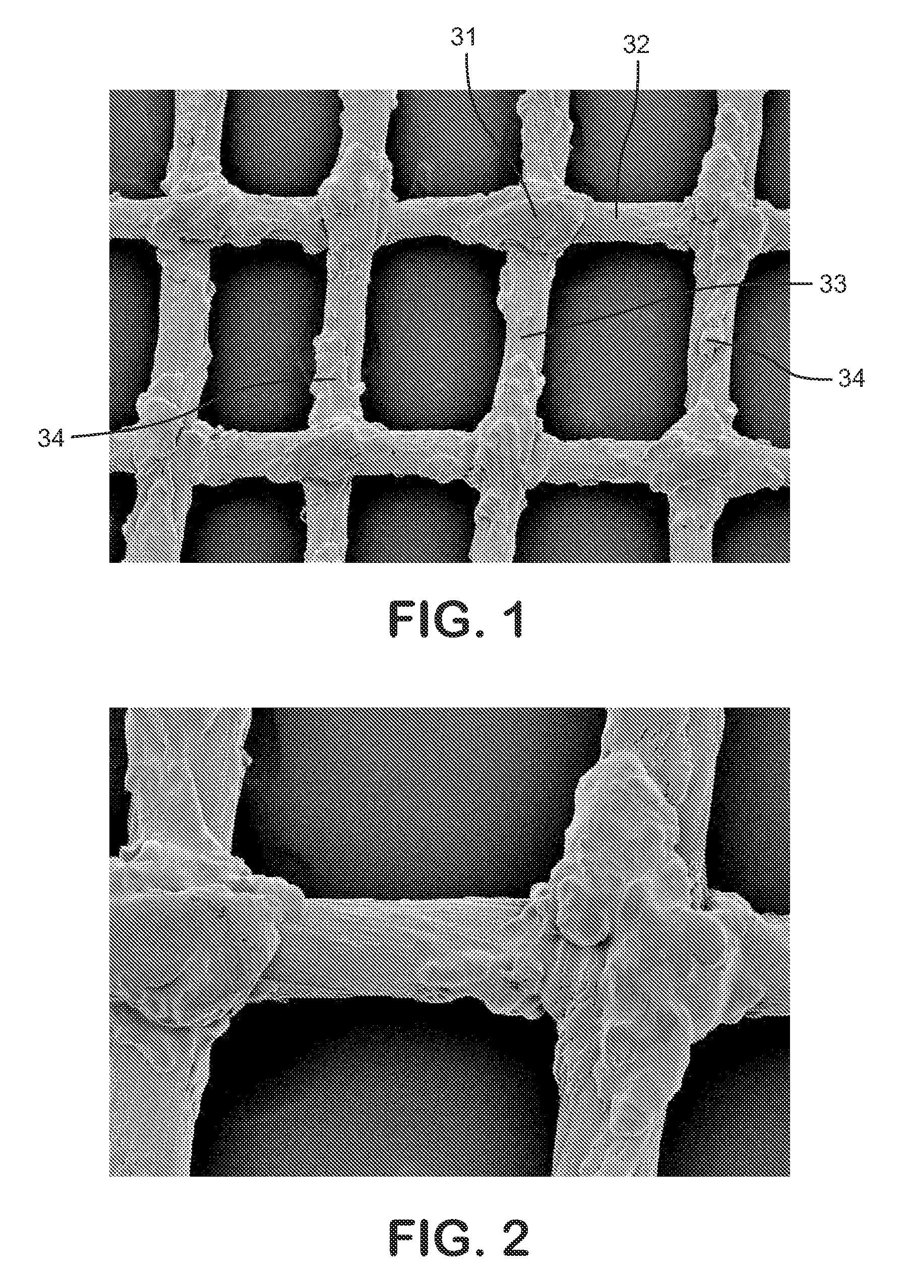
[0058]Nominal 90 denier (“d”) ePTFE round fiber was obtained (part # V112403; W.L. Gore & Associates, Inc., Elkton, Del.) and woven into a structure having the following properties: 31.5 ends / cm in the warp direction by 23.6 picks / cm in the weft direction.

[0059]This woven article was plasma treated with an Atmospheric Plasma Treater (model number ML0061-01, Enercon Industries Corp., Menonomee Falls, Wis.) using argon gas. The process parameters were: argon flow rate of 50 L / min, power source of 2.5 kW, line speed of 3 m / min, 7.6 cm electrode length, 10 passes. The woven plasma treated article was restrained on a pin frame and placed in a forced air oven (model number CW 7780F, Blue M Electric, Watertown, Wis.) set to 350 deg C. for 30 min.

[0060]The article was removed from the oven and quenched in water at ambient temperature, then it was examined with a scanning electron microscope. Scanning electron micrographs (“SEMs”) of the surface of this article appear in FIGS. 1 and 2 at mag...

example 1b

[0063]Nominal 90d ePTFE round fiber was obtained (part # V112403; W.L. Gore & Associates, Inc., Elkton, Del.), and a woven structure was formed with this fiber having the following properties: 31.5 ends / cm in the warp direction by 23.6 picks / cm in the weft direction.

[0064]The woven article was plasma treated with an Atmospheric Plasma Treater (model number ML0061-01, Enercon Industries Corp., Menonomee Falls, Wis.) using argon gas. The process parameters were: argon flow rate of 50 L / min, power source of 2.5 kW, line speed of 3 m / mini 7.6 cm electrode length, 10 passes.

[0065]The woven plasma treated article was restrained on a pin frame and placed in a forced air oven (model number CW 7780F, Blue M Electric, Watertown, Wis.) set to 350 deg C. for 15 min. The article was removed from the oven and quenched in water at ambient temperature, then the article was examined with a scanning electron microscope and tested for resistance to fraying (fiber removal) in accordance with the test m...

example 2

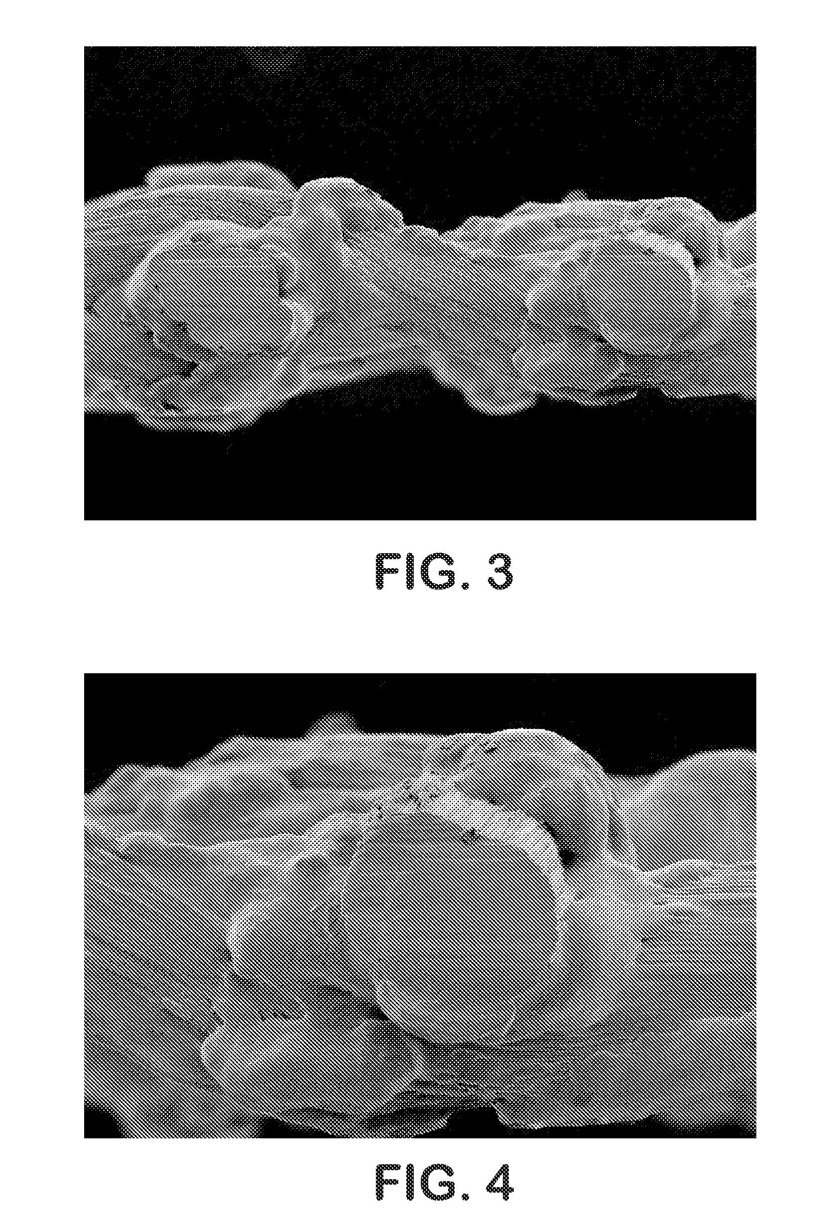
[0074]Nominal 90d ePTFE round fiber was obtained (part # V112403; W.L. Gore & Associates, Inc., Elkton, Del.), and a woven article was created with this fiber having the following properties: 49.2 ends / cm in the warp direction by 49.2 picks / cm in the weft direction.

[0075]The woven article was plasma treated with an Atmospheric Plasma Treater (model number ML0061-01, Enercon Industries Corp., Menomonee Falls, Wis.) using argon gas. The process parameters were: argon flow rate of 50 L / min, power source of 2.5 kW, line speed of 3 m / min, 7.6 cm electrode length, 5 passes.

[0076]The woven plasma treated article was restrained on a pin frame and placed in a forced air oven (model number CW 7780F, Blue M Electric, Watertown, Wis.) set to 350 deg C. for 15 min. The article was removed from the oven and quenched in water at ambient temperature.

[0077]The article was examined with a scanning electron microscope and tested for fray resistance using the fiber removal test described above. Scannin...


PUM

PropertyMeasurementUnit
Structureaaaaaaaaaa
Shapeaaaaaaaaaa

Abstract

Unique PTFE fabric structures, and methods for making same, are described which comprise a plurality of PTFE fibers overlapping at intersections, at least a portion of the intersections having PTFE masses which mechanically lock the overlapping PTFE fibers.

Description

FIELD OF THE INVENTION[0001]The present invention relates to unique PTFE fabric articles. More specifically, novel structures of PTFE and a novel process for preparing the structures are described.BACKGROUND OF THE INVENTION[0002]The structure of expanded PTFE (“ePTFE”) is well known to be characterized by nodes interconnected by fibrils, as taught in U.S. Pat. Nos. 3,953,566 and 4,187,390, to Gore, and which patents have been the foundation for a significant body of work directed to ePTFE materials. The node and fibril character of the ePTFE structure has been modified in many ways since it was first described in these patents. For example, highly expanded materials, as in the case of high strength fibers, can exhibit exceedingly long fibrils and relatively small nodes. Other process conditions can yield articles, for example, with nodes that extend through the thickness of the article.[0003]Surface treatment of ePTFE structure has also been carried out by a variety of techniques i...

Claims


Application Information

Patent Timeline
IPC IPC(8): B32B27/02D04B21/14D03D15/00D03D9/00D04H5/00B32B1/08B44C1/22
CPCD03D1/00D03D15/00D04B21/12D04H1/42D04H1/44Y10T428/1362D10B2321/042D10B2505/04D10B2509/00Y10T428/2913D04H1/465Y10T442/10Y10T442/425Y10T442/3089Y10T442/608D03D15/41D03D15/283D04B1/14D06M10/00D04H1/541D04H13/00D10B2401/063
Inventor CLOUGH, NORMAN ERNEST
Owner WL GORE & ASSOC INC
Why Eureka
Try Eureka