On-line replacement of dcfc tubular elements

a technology of tubular elements and tubular parts, which is applied in the direction of fuel cells, fuel cell details, electrical equipment, etc., can solve the problems of complete stack replacement, complete fuel cell system shutdown, and laborious process

Inactive Publication Date: 2010-06-24
SRI INTERNATIONAL
View PDF0 Cites 8 Cited by
  • Summary
  • Abstract
  • Description
  • Claims
  • Application Information

AI Technical Summary

Benefits of technology

[0006]In one embodiment, the present invention is directed towards a method for replacing at least one direct carbon fuel cell (DCFC) tube of a plurality of DCFC tubes in a fuel cell on-line. The method comprises detecting a degradation in performance of the at least one DCFC tube, removing said at least one DCFC tube while said fuel cell is still operating, re-furbishing said at least one DCFC tube and providing a refurbished DCFC tube while said fuel cell is still operating.

Problems solved by technology

As a result, when an individual fuel cell element within the stack fails, complete stack replacement is necessary.
Typically this process is very laborious requiring the entire fuel cell system to be shut down for days.
The consequence for shutting down the fuel cell system and repairing or replacing an individual fuel cell element comes at an enormous cost.

Method used


Image

  • On-line replacement of dcfc tubular elements
  • On-line replacement of dcfc tubular elements
  • On-line replacement of dcfc tubular elements

Examples


Embodiment Construction

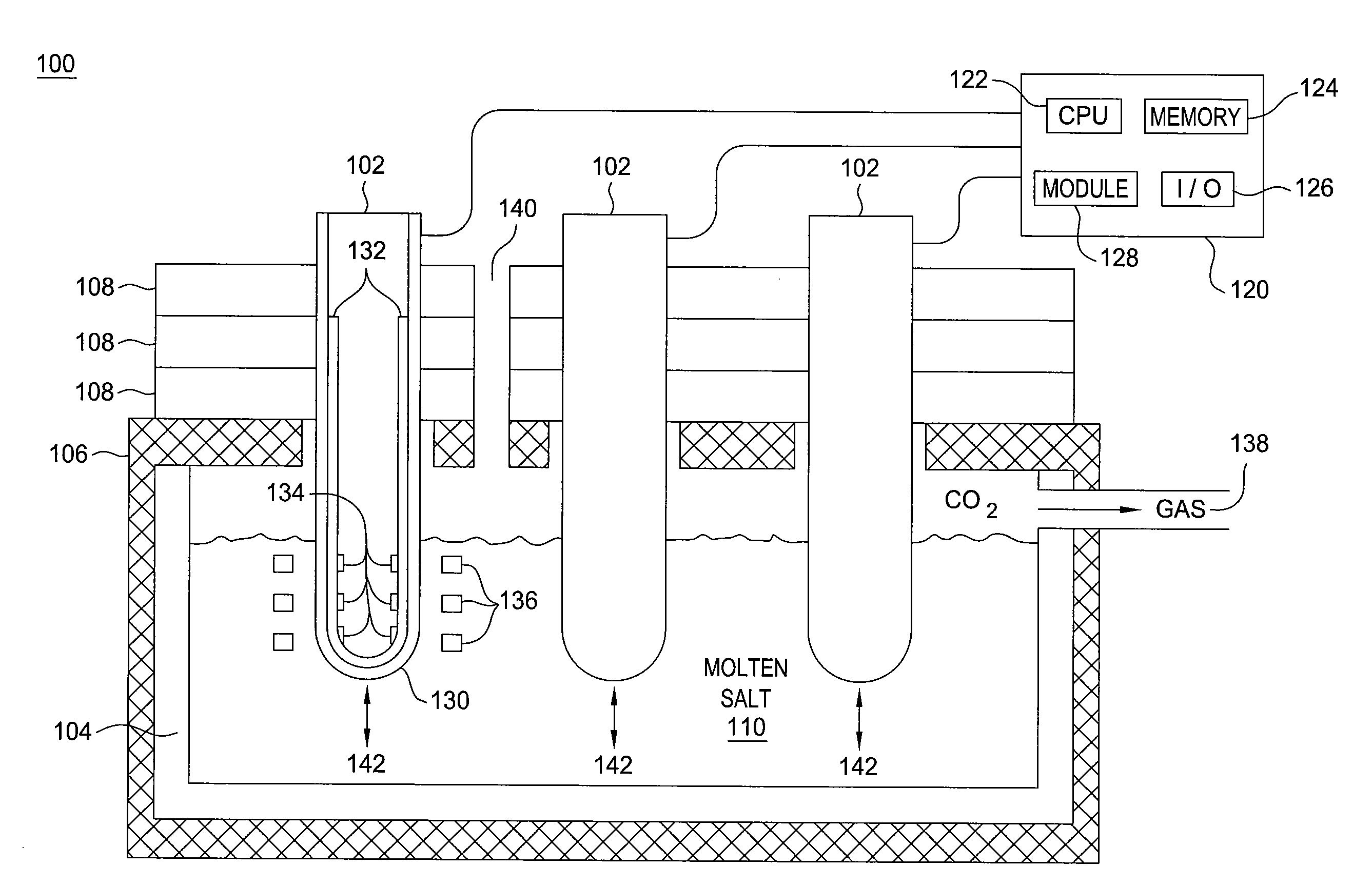
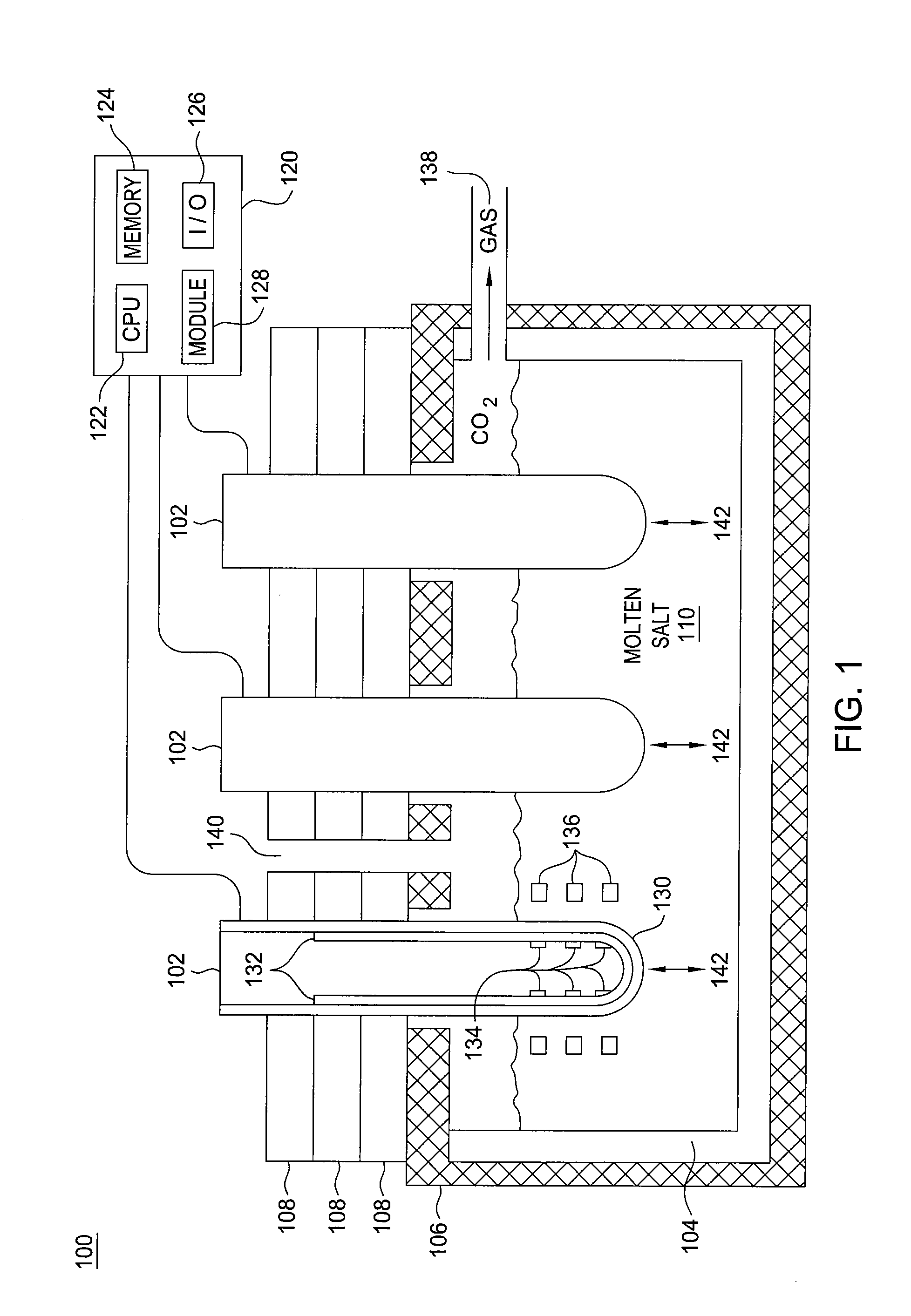
[0012]An illustrative fuel cell 100 of the present invention is illustrated in FIG. 1. In one embodiment, the fuel cell 100 comprises a plurality of direct carbon fuel cell (DCFC) tubes 102 inserted into a molten salt bath 110 in a vessel 104. Although FIG. 1 illustrates the use of three DCFC tubes 102, those skilled in the art will recognize that any number of DCFC tubes 102 may be used. Alternatively, the fuel cell 100 may comprise an array of vessels 104 each having one or more DCFC tubes 102.

[0013]In one embodiment, a thermal insulation layer 106 may be placed around the vessel 104. One or more holes may be provided in the thermal insulation layer 106 for removably inserting each one of the DCFC tubes 102. For example, a top view (not shown) of the fuel cell 100 may have multiple rows and columns of DCFC tubes 102 inserted through the thermal insulation layer 106. In addition, one or more removable thermal insulation layers 108 may be added on top of the thermal insulation layer...


PUM

PropertyMeasurementUnit
diameteraaaaaaaaaa
diameteraaaaaaaaaa
resistanceaaaaaaaaaa

Abstract

In one embodiment, the present invention relates generally to a method for replacing at least one direct carbon fuel cell (DCFC) tube of a plurality of DCFC tubes in a fuel cell on-line. In one embodiment, the method includes detecting a degradation in performance of the at least one DCFC tube, removing the at least one DCFC tube while the fuel cell is still operating and providing a replacement DCFC tube while the fuel cell is still operating.

Description

FIELD OF THE INVENTION[0001]The present invention relates generally to direct carbon fuel cells (DCFC) and a method and system for providing on-line replacement of DCFC tubular elements.BACKGROUND OF THE INVENTION[0002]Currently, most fuel cell technology use stacks. For example, the stack may be built with alternating layers of repeating parts. As a result, when an individual fuel cell element within the stack fails, complete stack replacement is necessary.[0003]Under the stack design, the entire system must be shut down for maintenance or to perform the stack replacement. For example, the fuel cell system is shut down to allow the entire system to cool. Then, the stack must be removed from the system and the failed fuel cell element may be repaired or replaced. Typically this process is very laborious requiring the entire fuel cell system to be shut down for days. The consequence for shutting down the fuel cell system and repairing or replacing an individual fuel cell element come...

Claims


Application Information

Patent Timeline
Patent Type & Authority Applications(United States)
IPC IPC(8): H01M8/04H01M8/02
CPCH01M8/0252H01M8/04365H01M8/04552H01M8/04582Y02E60/525H01M8/1233H01M8/22H01M8/2455Y02E60/521H01M8/04641Y02E60/50
Inventor WOLK, RONALDBALACHOV, IOURI
Owner SRI INTERNATIONAL
Why Eureka
Try Eureka