Aneurysm embolization device and operation method thereof

an aneurysm and embolization technology, applied in the field of aneurysm embolization device and operation method thereof, can solve the problems of fatal bleeding, blockage of blood flow, and aneurysm size increase, and achieve the effect of occluding aneurysm readily and reliably

Inactive Publication Date: 2010-06-24
TAKUMA NORIKATA
View PDF6 Cites 17 Cited by
  • Summary
  • Abstract
  • Description
  • Claims
  • Application Information

AI Technical Summary

Benefits of technology

[0029]Thus, the present invention can provide a method for operating an aneurysm embolization device, using the above-mentioned aneurysm embolization device, the method capable of occluding an aneurysm readily and reliably.

Problems solved by technology

If untreated, an aneurysm can increase in size, and eventually ruptures.
The rupturing of the aneurysm is likely to cause fatal bleeding: for example, bleeding onto the brain surface (subarachnoid hemorrhage).
All of such aneurysm treatments provide reduction in the blood flowing into the aneurysm and result in blockage of blood flow and formation of a clot.
Furthermore, the surgery may compress or damage the brain tissue.
However, it is very difficult to keep the balloon from deflating after the balloon is detached from the catheter, and it is also required to keep watch on the balloon not to deflate even after the separation.
As a result, the balloon is not able to occlude the aneurysm completely because the shape of the neck part of aneurysm and that of the balloon do not always match (i.e., the balloon is not able to correspond to various shapes of aneurysms).
Hei 06-107549, selection of a liquid substance to fill an aneurysm is difficult, because the liquid substance must be liquid until filled into the aneurysm and must promptly coagulate right after filled into the aneurysm.
However, packing of an aneurysm with a coil is difficult in the coil embolization technique, and there is also a risk of bleeding by breaking the aneurysm wall during a process of the operation.
Furthermore, there are risks that a part of the coil may stick out into the inside of the parent vessel, or that the coil packed in the aneurysm may escape into the parent vessel if the neck part of the aneurysm is wide.
Still furthermore, even if the coil is packed into the aneurysm completely, approximately half a space in the aneurysm remains unfilled.
The space may allow blood to flow in the aneurysm, and thus embolization could be failed in some cases.
In addition, the stent placement as represented by the inventions described in Japanese Patent Application Publication No. 2004-33535 and Japanese Patent No. 4057318 has a risk to block a way in other necessary branched blood vessel as well as the aneurysm if the blood vessel is branched around the site of the aneurysm.

Method used


Image

  • Aneurysm embolization device and operation method thereof
  • Aneurysm embolization device and operation method thereof
  • Aneurysm embolization device and operation method thereof

Examples


embodiment 1

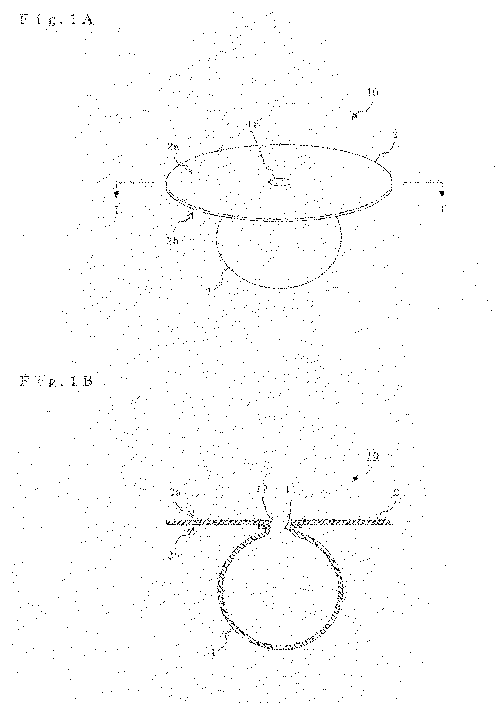
[0045]FIGS. 1A and 1B are diagram showing a structure of an aneurysm embolization device according to a first embodiment of the present invention. FIG. 1A is a perspective view showing the entire structure, and FIG. 1B is a longitudinal sectional view taken along the line I-I in FIG. 1A.

[0046]As shown in FIGS. 1A and 1B, the aneurysm embolization device 10 of this embodiment includes a balloon dome part 1 and a balloon plane part 2. Incidentally, FIGS. 1 A and 1B are shown schematically with slight exaggeration to facilitate the understanding of functions of the aneurysm embolization device of the present invention (including functions of both the balloon dome part and the balloon plane part).

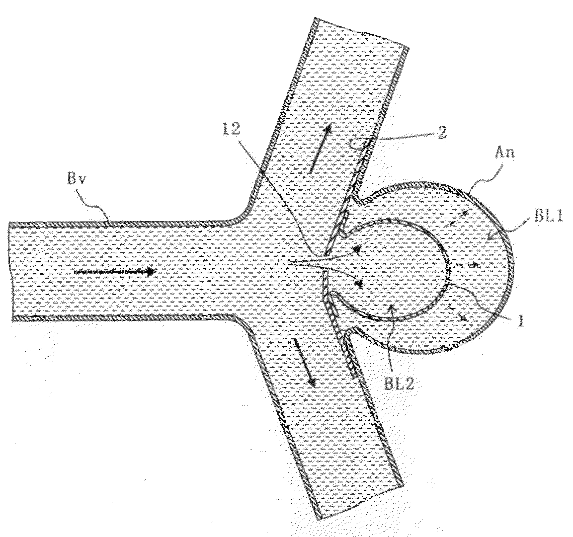
[0047]The balloon dome part 1 is a sac body, which is inserted into an aneurysm, expanded by influx of blood, and left in the aneurysm. This balloon dome part 1 is made of a flexible, stretchable and thin biocompatible material using, for example, latex or silicone. Additionally, it is desirabl...

embodiment 2

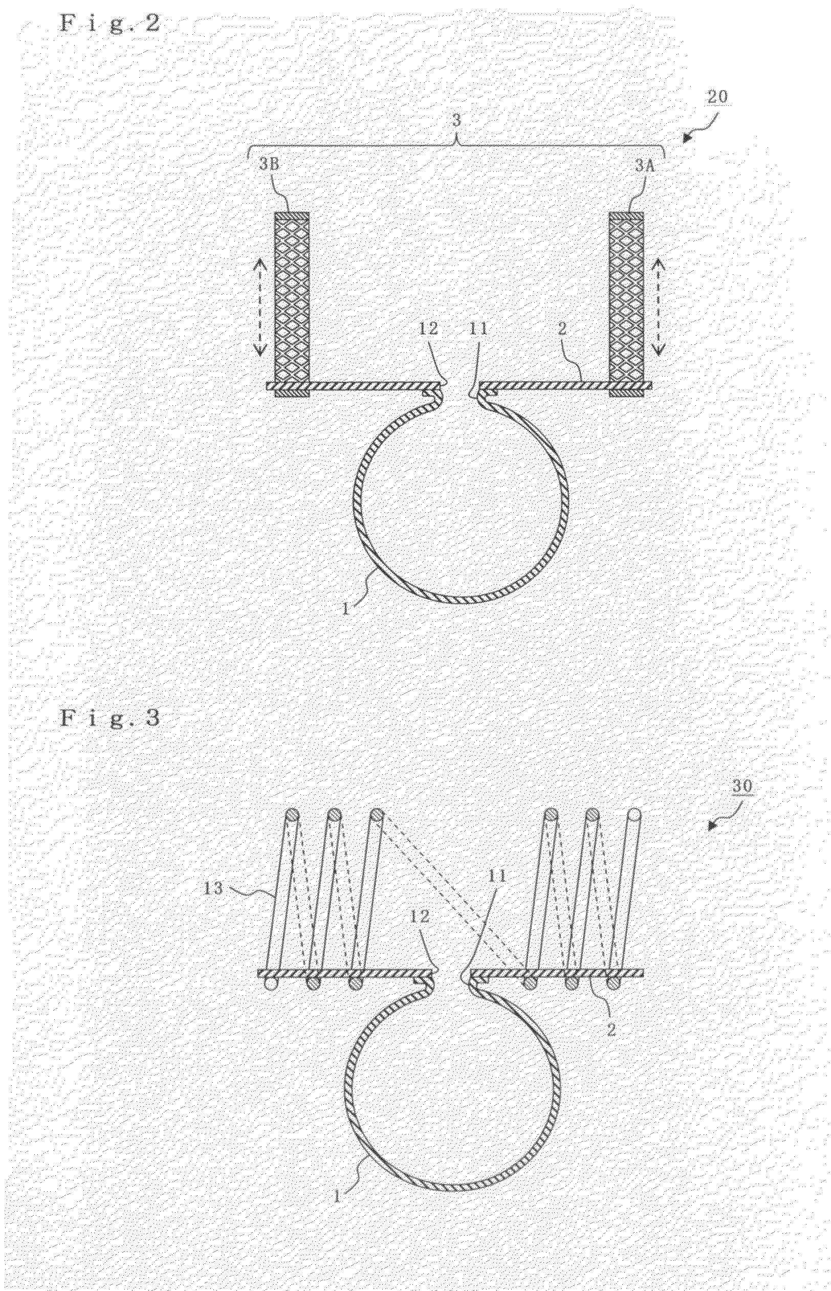
[0054]In the present invention, an aneurysm embolization device can be left in a blood vessel more stably. In other words, a second embodiment of the present invention is different from the above-described first embodiment in that the second embodiment includes means for stabilizing the balloon plane part 2 in a blood vessel.

[0055]Note that, in other embodiments to be described below, description will be given mainly of aspects which are different from those in the above-described first embodiment of the present invention. Therefore, the same letters or numerals are given to constituents which are similar to those in the first embodiment, and explanations thereof are omitted. The constituents represented by the same letters or numerals will be the same unless it is otherwise particularly described.

[0056]An aneurysm embolization device of this embodiment including mean for stabilizing the device in a blood vessel can be exemplified as shown in FIG. 2. The aneurysm embolization device...

embodiment 3

[0072]In the present invention, the influx of blood into the balloon dome part 1 can be ensured. In other words, the diameter of the opening 11 is a size that at least allows influx of blood from the hole 12 of the balloon plane part 2 in the above-described balloon dome part 1 of the first embodiment. However, if the diameter of the opening 11 is small, the opening 11 may be twisted during operation of the aneurysm embolization device; as a result, there is a risk to block influx of blood into the balloon dome part 1. Therefore, a third embodiment of the present invention is different from the above-described first embodiment in the structure of an opening 11 of a balloon dome part 1.

[0073]An aneurysm embolization device of this embodiment can be exemplified in FIG. 5.

[0074]As shown in FIG. 5, an aneurysm embolization device 40 of this embodiment includes the balloon dome part 1 and the balloon plane part 2. The balloon plane part 2 further has the hole 12 communicating with the in...


PUM


Abstract

An aneurysm embolization device includes at least: a sac-shaped balloon dome part which is inserted into the aneurysm, then expanded and left therein; and a balloon plane part which is provided at an opening of the balloon dome part and covers a mouth part of the aneurysm. The balloon plane part has a hole communicating with the inside of the balloon dome part. The aneurysm embolization device thus constituted is housed into a lumen of a protective outer sheath member formed of a flexible elongated-body having the lumen therein. A tip part of the protective outer sheath member is placed at a desired position, and the aneurysm embolization device is ejected from the tip part of the protective outer sheath member. The aneurysm embolization device thus ejected includes the balloon dome part placed at a desired position and the balloon plane part deploying to cover the desired position.

Description

BACKGROUND OF THE INVENTION[0001]1. Field of the Invention[0002]The present invention relates to an aneurysm embolization device for treating an aneurysm in a blood vessel by occluding the aneurysm, and an operation method thereof. Specifically, the present invention relates to techniques for treating an aneurysm according to the site, the size, the shape, and the like of the aneurysm.[0003]2. Description of the Related Art[0004]An aneurysm is local dilatation of a blood vessel due to weakening of the vascular wall, and usually has a size of 3 mm to 4 mm, or sometimes of 15 mm or larger in diameter. If untreated, an aneurysm can increase in size, and eventually ruptures. The rupturing of the aneurysm is likely to cause fatal bleeding: for example, bleeding onto the brain surface (subarachnoid hemorrhage). A clipping method and intravascular surgical techniques are known for treating such aneurysms.[0005]The clipping method is a surgical technique that blocks blood from flowing into ...

Claims


Application Information

Patent Timeline
Patent Type & Authority Applications(United States)
IPC IPC(8): A61M29/00A61B17/12A61M25/10A61M29/02
CPCA61B17/12113A61B17/12118A61F2002/823A61B2017/1205A61F2/82A61B17/12136
Inventor TAKUMA, NORIKATA
Owner TAKUMA NORIKATA
Why Eureka
Try Eureka