Aneurysm embolization device

Inactive Publication Date: 2011-07-28
TAKUMA NORIKATA
View PDF33 Cites 0 Cited by
  • Summary
  • Abstract
  • Description
  • Claims
  • Application Information

AI Technical Summary

Benefits of technology

[0022]The present invention addresses the problems discussed above. An object of the present invention is to provide an aneurysm embolization device capable of occluding an aneurysm readily and reliably in an appropriate manner according to an onset site of the aneurysm, the shape of a neck part of the aneurysm, and the size thereof, and also capable of treating an aneurysm, even when a blood vessel branches from the aneurysm itself, without occluding an entrance of the branched blood vessel.
[0034]Accordingly, when the aneurysm embolization device is placed so that the balloon dome part can be inserted into an aneurysm having a blood vessel branching from the aneurysm itself, the balloon plane part is left on the mouth part of the aneurysm. Therefore, the balloon plane part can cover a desired region around the aneurysm as well as the mouth part and regardless of the shape and size of the mouth part. Moreover, the first hole provided to the balloon plane part allows blood flowing inside a parent blood vessel to flow into the balloon dome part. In this event, when the balloon dome part is expanded by the blood flowing in through the first hole, the gap forming member provided to the balloon dome part serves as a spacer for forming a partial gap between the outer surface of the balloon dome part and the inner surface of the aneurysm. This gap formed outside the balloon dome part and from the second hole of the balloon plane part to the branched blood vessel prevents the balloon dome part from occluding the entrance to the branched blood vessel.
[0035]As a result, the stream of the blood flowed into the balloon dome part is repressed by covering and closing the aneurysm with the balloon plane part, and thus, the blood in the balloon dome part forms a clot to occlude the aneurysm. In addition, because of the clot formation by the blood in the balloon dome part, the balloon dome part prevents the aneurysm embolization device from being swept away by the blood flow, thus functioning as an anchor member to aid the remaining of the device at the site of aneurysm. Furthermore, blood from the parent blood vessel flows into the gap formed between the outer surface of the balloon dome part and the inner surface of the aneurysm through the second hole of the balloon plane part. Then, the gap guides the blood to the branched blood vessel. Accordingly, the blood flowing inside the parent blood vessel flows into the branched blood vessel without being blocked. Thus, the blood flow can be secured. In this case, the blood flow is secured the most in the shortest distance between the second hole and the branched blood vessel, whereas, at a position far away from this blood flowing portion, the blood flow stagnates and a clot is formed. Especially, at a position inside the aneurysm which is on an opposite side of the part where the branched blood vessel starts, the blood flow stagnates, resulting in an early-stage development of blood clot.
[0036]Thus, it is possible to provide an aneurysm embolization device capable of occluding an aneurysm readily and reliably in an appropriate manner according to an onset site of the aneurysm, the shape of a neck part of the aneurysm, and the size thereof, and also capable of treating an aneurysm, even when a blood vessel branches from the aneurysm itself, without occluding the entrance to the branched blood vessel.

Problems solved by technology

If untreated, an aneurysm can increase in size, and eventually ruptures.
The rupturing of the aneurysm is likely to cause fatal bleeding: for example, bleeding onto the brain surface (subarachnoid hemorrhage).
All of such aneurysm treatments provide reduction in the blood flowing into the aneurysm and result in blockage of blood flow and formation of a clot.
Furthermore, the operation may compress or damage the brain tissue.
However, it is very difficult to keep the balloon from deflating after the balloon is detached from the catheter, and it is also required to keep watch on the balloon not to deflate even after the separation.
As a result, the balloon is not able to occlude the aneurysm completely because the shape of the neck part of aneurysm and that of the balloon do not always match (i.e., the balloon is not able to correspond to various shapes of aneurysms).
Hei 06-107549, selection of a liquid substance to fill an aneurysm is difficult, because the liquid substance must be liquid until filled into the aneurysm and must promptly coagulate right after filled into the aneurysm.
However, packing of an aneurysm with a coil is difficult in the coil embolization, and there is also a risk of bleeding by breaking the aneurysm wall during a process of the operation.
Furthermore, there are risks that a part of the coil may stick out into the parent blood vessel, or that the coil packed in the aneurysm may escape into the parent blood vessel if the neck part of the aneurysm is wide.
Still furthermore, even if the coil is packed into the aneurysm completely, approximately half a space in the aneurysm remains unfilled.
The space may allow blood to flow in the aneurysm and thus embolization could be failed in some cases.
In addition, the stent placement as represented by the inventions described in Japanese Patent Application Publication No. 2004-33535 and Japanese Patent No. 4057318 has a risk to block a way in other necessary branched blood vessel as well as the aneurysm if the blood vessel branches around the site of the aneurysm.
However, even the aneurysm embolization devices disclosed in Japanese Patent Nos. 4312255 and 4334611 may not be able to cope with a situation where there is a branched blood vessel inside an aneurysm.

Method used


Image

  • Aneurysm embolization device
  • Aneurysm embolization device
  • Aneurysm embolization device

Examples


embodiment 1

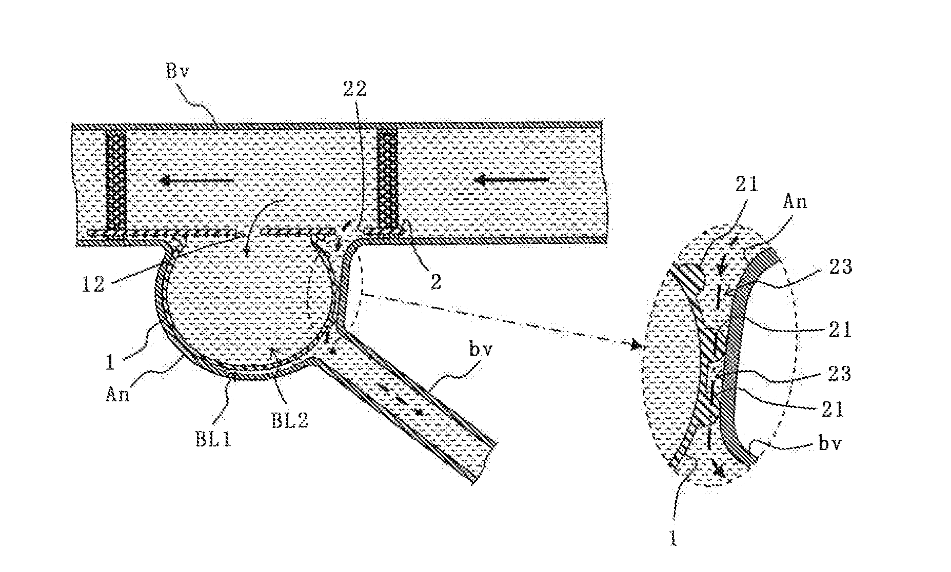
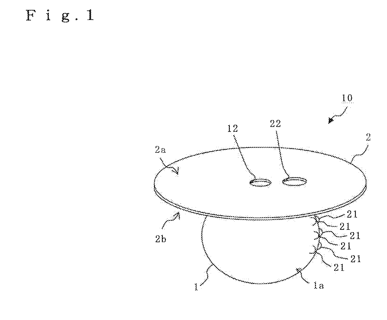
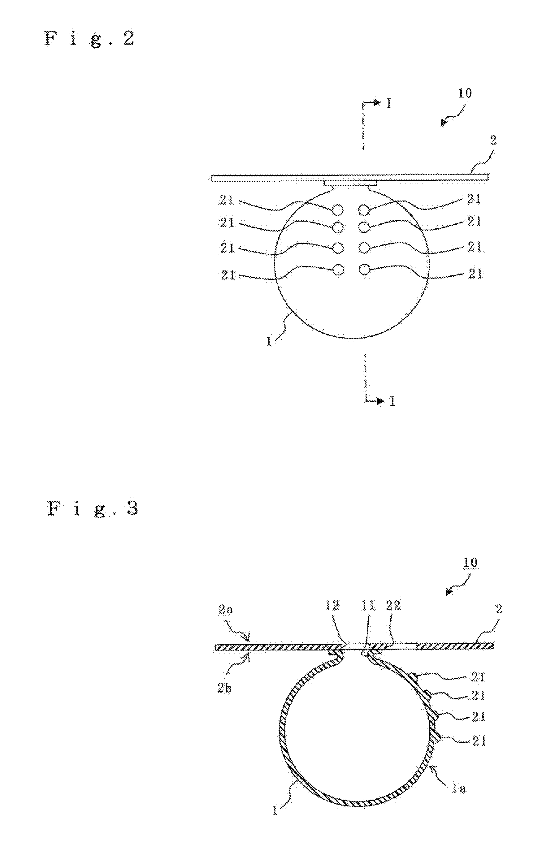
[0060]As shown in FIGS. 1 to 3, the aneurysm embolization device 10 of the present embodiment includes a balloon dome part 1 and a balloon plane part 2. Incidentally, FIG. 1 is shown schematically with slight exaggeration to facilitate the understanding of functions of the aneurysm embolization device of the present invention (including functions of both the balloon dome part and the balloon plane part).

[0061]The balloon dome part 1 is a sac body, which is inserted into an aneurysm, expanded by influx of blood, and left in the aneurysm. This balloon dome part 1 is made of a flexible, stretchable and thin biocompatible material using, for example, latex or silicone rubber. Additionally, it is desirable that the entire outside diameter of the balloon dome part 1 be almost equal to or slightly smaller than the inside diameter of the aneurysm.

[0062]The balloon dome part 1 includes gap forming members 21. The gap forming members 21 have a function of forming a desired non-contact space w...

embodiment 2

[0078]In the present invention, the influx of blood into the balloon dome part 1 can be ensured. In other words, the diameter of the opening 11 is a size that at least allows influx of blood from the influx hole 12 of the balloon plane part 2 in the above-described balloon dome part 1 of the first embodiment. However, if the diameter of the opening 11 is small, the opening 11 may be twisted during operation of the aneurysm embolization device; as a result, there is a risk to block influx of blood into the balloon dome part 1. Therefore, a third embodiment of the present invention is different from the above-described first embodiment in the structure of an opening 11 of a balloon dome part 1.

[0079]Note that, in other embodiments to be described below, description will be given mainly of aspects which are different from those in the above-described first embodiment of the present invention. Therefore, the same letters or numerals are given to constituents which are similar to those i...

embodiment 3

[0083]In the present invention, an aneurysm embolization device can be left in a blood vessel more stably. In other words, a third embodiment of the present invention is different from the above-described first and second embodiments in that the third embodiment includes means for stabilizing the balloon plane part 2 in a blood vessel.

[0084]Note that, in other embodiments described below, description will be given by taking, as an example, the balloon dome part 1 having a structure with the opening 11 described in the second embodiment.

[0085]An aneurysm embolization device of the present embodiment including mean for stabilizing the device in a blood vessel can be exemplified as shown in FIG. 6. The aneurysm embolization device shown here has a beneficial effect on usage for a type of aneurysm which is exerted from a side surface of a blood vessel, for example.

[0086]As shown in FIG. 6, an aneurysm embolization device 30 of the present embodiment includes the balloon dome part 1 and ...


PUM


Abstract

An aneurysm embolization device includes at least: a sac-shaped balloon dome part which is inserted into an aneurysm in a blood vessel, then expanded and left therein; and a balloon plane part which is provided at an opening of the balloon dome part and covers an aneurysm mouth part. The balloon plane part includes: a first hole and a second hole communicating with the inside and the outside of the balloon dome part, respectively. The balloon dome part includes a gap forming member which forms a non-contact region where, when the balloon dome part is expanded in the aneurysm, an outer surface of the balloon dome part does not come into contact with an inner surface of the aneurysm. When the aneurysm embolization device is placed and deployed in an aneurysm having a blood vessel branching therefrom, a gap is formed between the outer surface of the balloon dome part and the inner surface of the aneurysm. Thus, a treatment for the aneurysm can be carried out without occluding an entrance of the branched blood vessel.

Description

BACKGROUND OF THE INVENTION[0001]1. Field of the Invention[0002]The present invention relates to an aneurysm embolization device for treating an aneurysm in a blood vessel by occluding the aneurysm. Specifically, the present invention relates to techniques allowing a treatment for an aneurysm to be carried out even when a blood vessel branches from the aneurysm itself.[0003]2. Description of the Related Art[0004]An aneurysm is local dilatation of a blood vessel due to weakening of the vascular wall, and usually has a size of 3 mm to 4 mm, or sometimes of 15 mm or larger in diameter. If untreated, an aneurysm can increase in size, and eventually ruptures. The rupturing of the aneurysm is likely to cause fatal bleeding: for example, bleeding onto the brain surface (subarachnoid hemorrhage). A clipping method and intravascular surgical techniques are known for treating such aneurysms.[0005]The clipping method is a surgical technique that blocks blood from flowing into an aneurysm and e...

Claims


Application Information

Patent Timeline
IPC IPC(8): A61M29/00
CPCA61B17/0057A61B2017/00632A61B2017/00592
Inventor TAKUMA, NORIKATA
Owner TAKUMA NORIKATA
Why Eureka
Try Eureka