Mobile, expandable disaster shelter

a disaster shelter and expandable technology, applied in the field of mobile, expandable, disaster shelters, can solve the problems of unable to adequately provide the space requirements of displaced families, the size of recreation vehicles is relatively small, and the size of protective buildings/shelters cannot meet the needs of displaced families, so as to maximize the size of the extension, the effect of minimizing the movement of parts and joints and more structural sound

Inactive Publication Date: 2010-07-01
BONEBRAKE JEFFREY M
View PDF6 Cites 21 Cited by
  • Summary
  • Abstract
  • Description
  • Claims
  • Application Information

AI Technical Summary

Benefits of technology

[0014]An objective of the present invention is to provide a room extension system intended to offer medium term housing to victims of disasters. This system is intended to minimize moving parts and joints so as to make it more structurally sound. The unique feature of the system is that it does not slide out of the base structure thus limiting the size of the extension, but rather slides over the base structure thus maximizing the size of the extension. The system features a support floor which folds down from the side of the base structure providing a flat floor throughout the structure. The expandable sides then slide out over the base structure supported by the floor that was previously deployed. The deployment can be performed by two people in less than ten minutes without the use of hydraulic, pneumatic or electric assistance meaning no motor is required.

Problems solved by technology

The most obvious limitation of recreational vehicles is their relatively small size resulting from the width restrictions of a normal road or highway.
There have been many variations of slide-out room extensions but none of those adequately provide the space requirements to house a displaced family.
Moreover, recreational vehicles and other types of expandable structures generally due not meet the stringent governmental structural requirements.
U.S. Pat. No. 5,797,224 of Ray R. Gunthardt describes a multitude of structures composed of many intricate parts and mechanism, all of which would create a great deal of weight and be very complicated to erect.
Moreover, it does not provide a flat floor limiting its functionality for people in wheelchairs.
The variable height results in a seam around the middle of the structure lending itself to air and water leaks and brings into question its structural stability.

Method used


Image

  • Mobile, expandable disaster shelter
  • Mobile, expandable disaster shelter
  • Mobile, expandable disaster shelter

Examples


Embodiment Construction

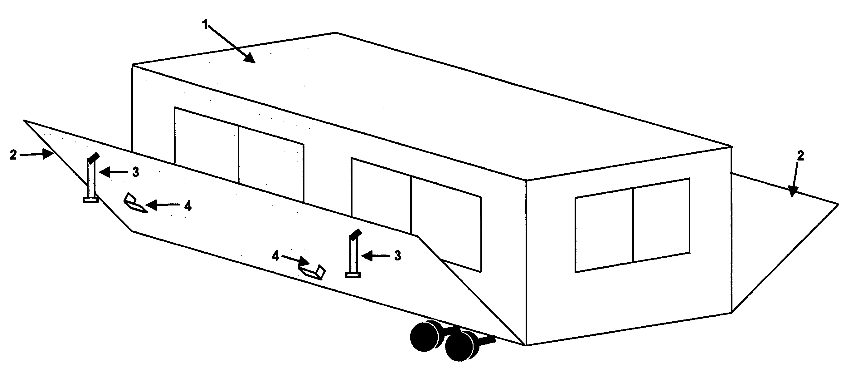
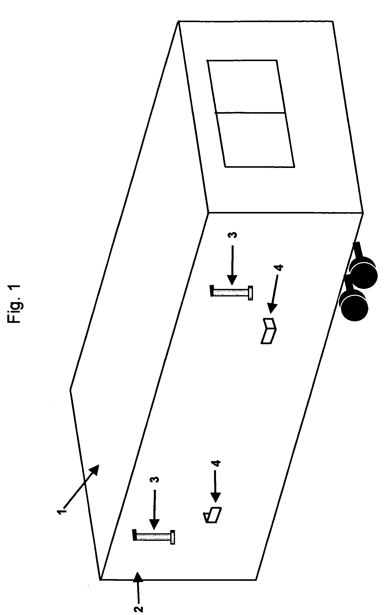
[0016]FIG. 1 shows the collapsed state of the base trailer. The fold down panel 2 forms the exterior wall in the collapsed state and will serve as the floor in the expanded state. Item 1 is the left shell of the structure. Items 3 are the adjustable support arms. Items 4 are the brackets that will receive the floor pivot arms.

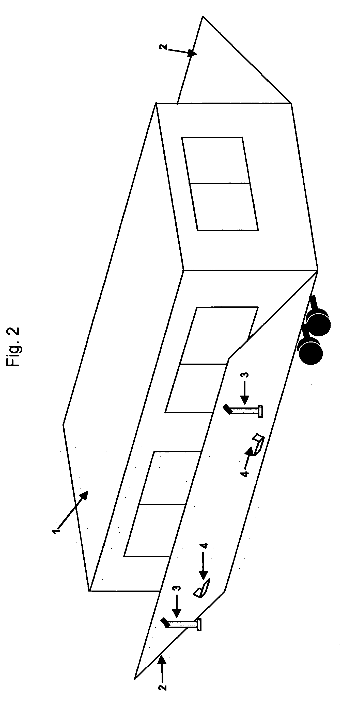
[0017]FIG. 2 depicts panel 2 folding down on both the left and right sides of the structure. This view further reveals item 1, the left shell of the structure.

[0018]FIG. 3 shows the floor panels 2 fully deployed. The adjustable support arms 3 have been locked in place. The floor brackets 4 are shown dotted as they are on the underside of floor panel 2. Note that the left shell 1 has not moved at this point.

[0019]FIG. 4 illustrates the brackets 4 and the locking swing arms 5 that are located below the folding floor panels 2 and the base floor panel 8. Shell 1 is not shown for ease of interpretation. The swing arms 5 will simply pivot 90 degrees resting in bracke...


PUM


Abstract

The invention encompasses a mobile, expandable shelter intended to provide medium term housing to disaster victims. The invention minimizes moving parts so as to make the shelter more structurally sound and allows full deployment by two people in less than ten minutes without the use of a motor to supply hydraulic, pneumatic or electric assistance. This shelter will maximize space by offering the unique feature of side shells that slide over the base structure not out of the base structure.

Description

CROSS-REFERENCE TO RELATED APPLICATIONS[0001]Not ApplicableSTATEMENT REGARDING FEDERALLY SPONSERED RESEARCH OR DEVELOPMENT[0002]Not ApplicableREFERENCE TO SEQUENCE LISTING, A TABLE, OR A COMPUTER PROGRAM LISTING COMPACT DISC APPENDIX[0003]Not ApplicableBACKGROUND OF THE INVENTION[0004]The present invention relates to a mobile, expandable, disaster shelter that would serve as medium-term housing for victims of a disaster.[0005]Recreational vehicles were utilized as medium term emergency housing after hurricane Katrina. The most obvious limitation of recreational vehicles is their relatively small size resulting from the width restrictions of a normal road or highway. There have been many variations of slide-out room extensions but none of those adequately provide the space requirements to house a displaced family. Moreover, recreational vehicles and other types of expandable structures generally due not meet the stringent governmental structural requirements.[0006]In addition to bein...

Claims


Application Information

Patent Timeline
Patent Type & Authority Applications(United States)
IPC IPC(8): E04H1/02
CPCE04B1/34305
Inventor BONEBRAKE, JEFFREY M.
Owner BONEBRAKE JEFFREY M
Why Eureka
Try Eureka