Eureka AIR delivers breakthrough ideas for toughest innovation challenges, trusted by R&D personnel around the world.

Flow rate sensor for water ducts and a method for measuring water flow

Inactive Publication Date: 2010-07-01
ACQUE INGEGNERIA +1
View PDF26 Cites 0 Cited by
  • Summary
  • Abstract
  • Description
  • Claims
  • Application Information

AI Technical Summary

Benefits of technology

[0007]Therefore, it is a feature of the invention to provide a water flow rate sensing device for water ducts, having a thermal flow rate sensor, which is of quick and easy installation without stopping the water flow.

Problems solved by technology

Such sensors, moreover, preferably communicate the measured data to a control system, causing, in the known devices, high costs for creating cable connections with the result of a too low number of sensors mounted in a pipeline, sometimes insufficient for a precise flow control.
Furthermore, known sensors that exploit this thermo-dynamic principle have the drawback that, during the measure, the heat of the resistor produces vapour bubbles, which in part remain attached to the sensor and in part are removed by the flow.
Such bubbles, create an insulation around the sensor and negatively affect the flow measurements.

Method used


Image

  • Flow rate sensor for water ducts and a method for measuring water flow
  • Flow rate sensor for water ducts and a method for measuring water flow
  • Flow rate sensor for water ducts and a method for measuring water flow

Examples


Embodiment Construction

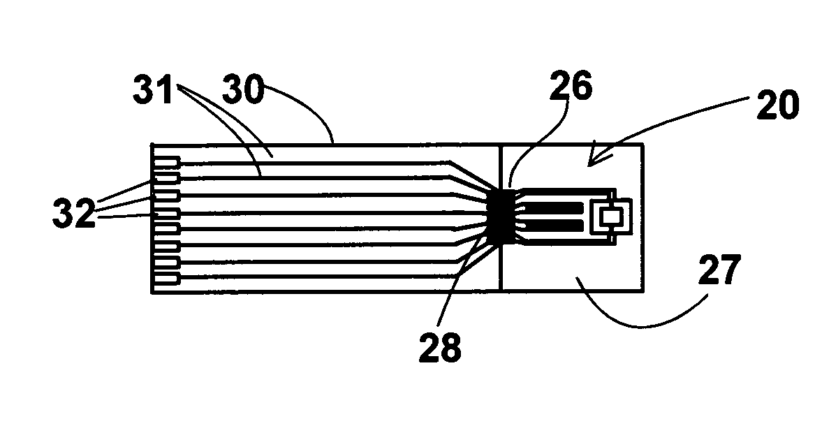
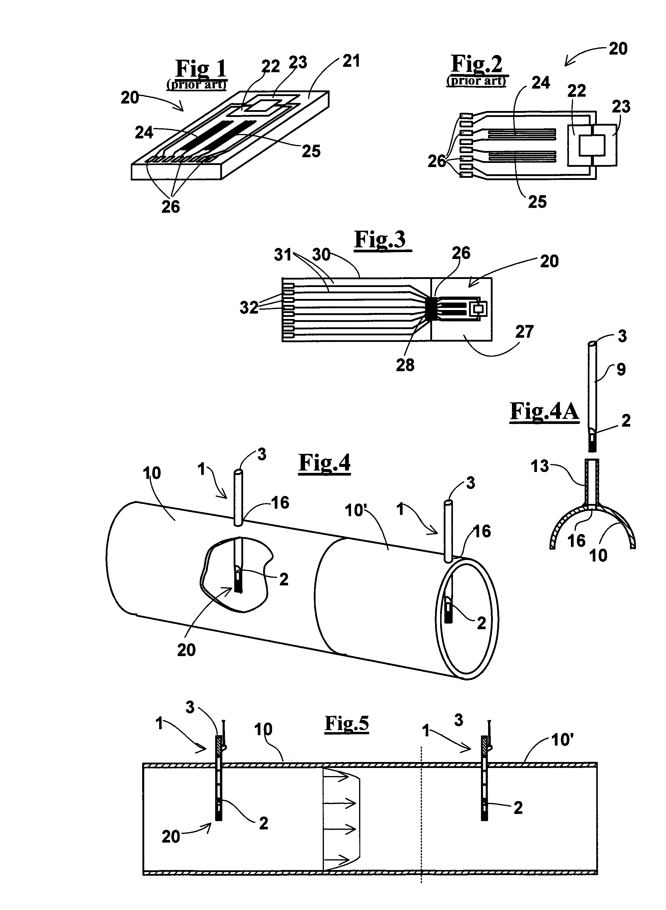
[0061]With reference to FIGS. 1 and 2, a known flow rate sensor 20 is described, whose operation is based on the measurement of removal of heat, which is provided by a resistor, by the water that flows in the duct where the sensor is mounted. Such a sensor has a support plate 21 and comprises at least one heater, 24 and 25, and at least one thermoresistance, 22 and 23, mounted on distinct circuits having respective contact pads at an end. In an exemplary embodiment, the two thermoresistances 22 and 23 can be interdigited to each other creating a single central rectangle, as described in U.S. Pat. No. 6,494,090. This way the detected signal allows discriminating the direction of the flow, being thermoresistances 22 and 23 interdigited, and at the same temperature, coincident to that of the water, and being a heater 25 located upstream from the flow same and the other heater 24 downstream of it. This arrangement requires that the second heater 24 exchanges less heat owing to the conve...


PUM

PropertyMeasurementUnit
Temperatureaaaaaaaaaa
Electric energyaaaaaaaaaa

Abstract

A water flow rate sensing device for water ducts, comprising a thermal sensor (20) capable of measuring the flow by measuring the removal of heat by a heater from the water; an elongated support (9) / in particular, tubular, having the sensor (20) mounted at a free end thereof so that the support is inserted laterally with respect to the duct through a hole and cantilevered in order to keep the sensor in a central zone of the duct. The free end of the support comprises a lamina-shaped extension member. Furthermore, the device comprises means (5,7) for transmitting a measuring signal to a remote control unit. The invention comprises also a method for measuring the water flow.

Description

FIELD OF THE INVENTION [0001]The present invention relates to devices for measuring physical parameters of a fluid flow and, in particular, it relates to a flow rate sensor for water flowing in water ducts.BACKGROUND OF THE INVENTION[0002]The need is felt of measuring the flow rate in pipes of water ducts and, in particular, of testing flow data in the same, on the one hand for checking the water consumption in the net and on the other hand for determining where large water losses or break of ducts occur.[0003]For monitoring the flow, many sensors should be provided along the pipes of a net, and such sensors should be very cheap and easy to clean or to change without the need of stopping the flow.[0004]Many sensors exist, of different nature, capable of measuring the flow rate in ducts. Among them thermal electronic solid state sensors exist capable of measuring the flow by measuring the heat transferred by a resistor to a liquid and, in particular, the temperature difference betwee...

Claims


Application Information

Patent Timeline
IPC IPC(8): G01F1/69B23P17/04
CPCG01F1/684G01F1/69Y10T29/49826
Inventor LANGE, PETERBERTINI, LORENZOMELANI, MASSIMILIANOBRANCHITTA, FRANCESCO
Owner ACQUE INGEGNERIA
Why Eureka
Eureka Blog
Learn More