Sound maximizing ammellescope

Inactive Publication Date: 2010-07-01
JIANG HUA DAVID
View PDF8 Cites 0 Cited by
  • Summary
  • Abstract
  • Description
  • Claims
  • Application Information

AI Technical Summary

Benefits of technology

[0010]In the first aspect, a human position this device next to his/her ear. Press chamber 1 tightly to his/her ear. He then slide chamber 2 against chamber 1, chamber 3 against chamber 2. Therefore, he or she maximize and minimize the sound wave entered by increasing and decreasing the density ratio between two adjacent chambers. Sound wave energy is multiplied and no

Problems solved by technology

The invention of battery free sound magnifier devices has become a challenging journey.
It provided a challenge to inventors, however, i.e. weak sound which is generated from miles away and which populates to a human ear by air molecules can not be heard or processed by these devices.
This ability is jeopardized by too low an air compression ratio when the subject is on an airplane which is taking off.
It limited the study to membrane material and carbon particles.
It, however, never used connected chambers to compress air to a peak ratio to maximize sound output.
It is therefore challenging to convert these vibrations to an electrical signal that is pure and simple.

Method used


Image

  • Sound maximizing ammellescope
  • Sound maximizing ammellescope
  • Sound maximizing ammellescope

Examples


first embodiment

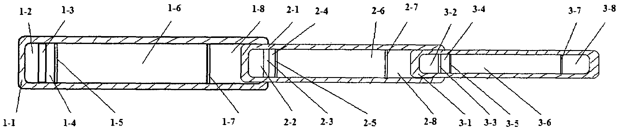
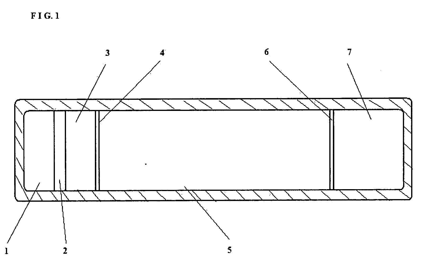
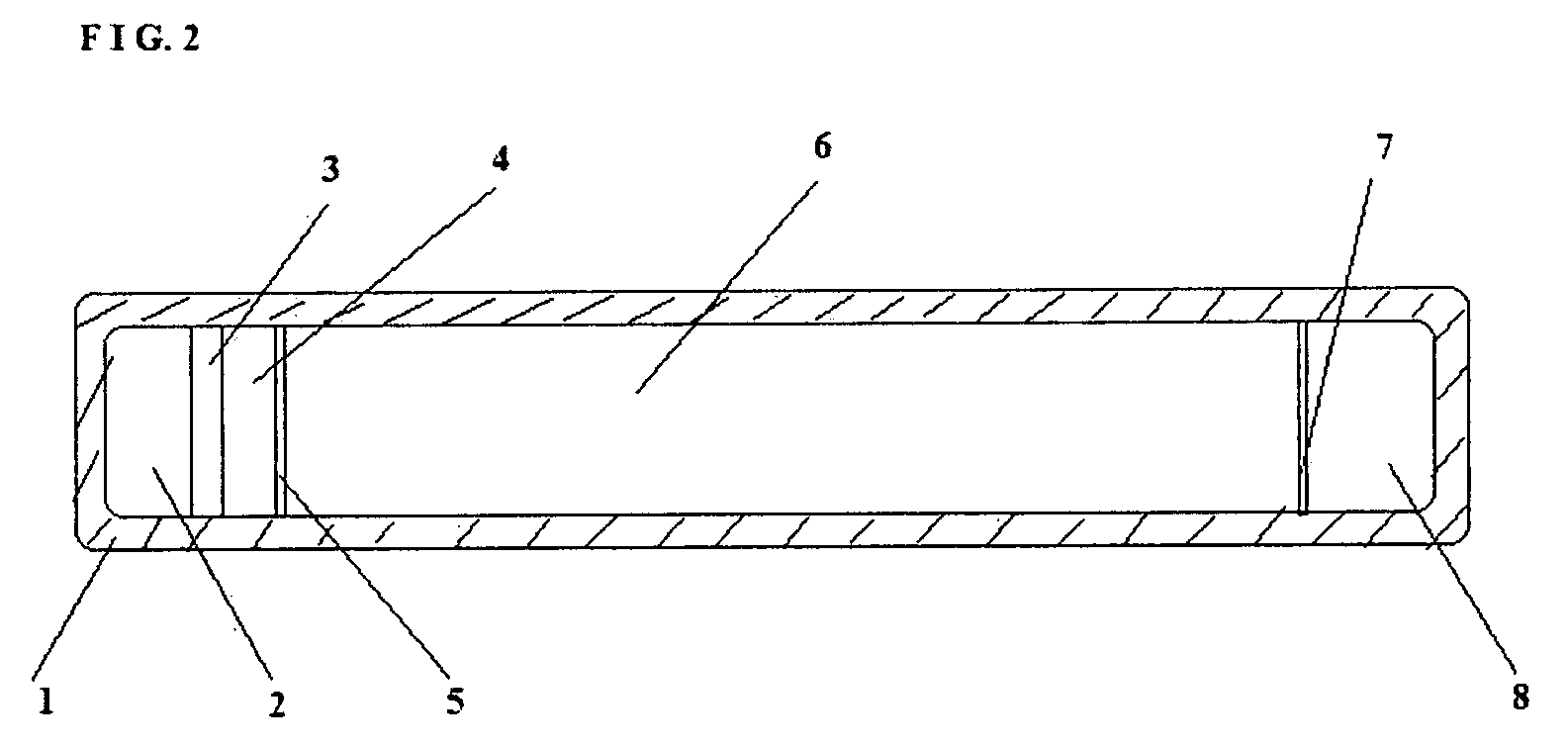
[0018]Device holder press Chamber 1 to his / her ear. Chamber 1 contains chip 1-3 which has multiple small holes to amplify the sound wave. It contains membrane 1-5 which works together with membrane 1-7 to compress the air inside Chamber 1 and between them.

second embodiment

[0019]Device holder press Chamber 2 against Chamber 1. Chamber 2 contains chip 2-3 which has multiple small holes to amplify the sound wave. It contains membrane 2-5 which works together with membrane 2-7 to compress the air inside Chamber 2 and between them.

third embodiment

[0020]Device holder press Chamber 3 against Chamber 2. Chamber 3 contains chip 3-3 which has multiple small holes to amplify the sound wave. It contains membrane 3-5 which works together with membrane 3-7 to compress the air inside Chamber 3 and between them.

[0021]Three chambers work together form air compression ratios between 1-6 and 2-6, and between 2-6 and 3-6. Air is prefilled in the space 1-6, 2-6, 3-6. These three air bodies contain air molecules that will react to pressure and to sound wave vibration. When the air molecules are under higher pressure, they are more active and then populate sound wave at a faster rate and higher quality.

[0022]Weak sound from long distance travels faster in 2-6 than in 3-6, even faster in 1-6 than in 2-6. Air molecules in 2-6 are more active than those in 3-6. Air molecules in 1-6 are more active than those in 2-6.

[0023]For example, the device operator slides Chamber 3, i.e., 3-1 body inward to Chamber 2, i.e., 2-1 body. The air pressure ratio ...


PUM


Abstract

In this device, three chambers, three chips with multiple holes and three membranes senses and magnifies sound signal from miles away to a magnitude that can be heard by device holder. Sound wave enter from the membrane, vibration energy is transmitted by highly compressed air within chamber 3, which then is magnified by multiple small holes in its chip. The same vibration is magnified by compressed air in chamber 2, which then is magnified by multiple small holes in its chip. Then the vibration is magnified by compressed air in chamber 1, which then is magnified by multiple small holes in its chip. Device holder adjust the air density in chamber 1, 2 and 2 by sliding chamber 3 inside chamber 2, and by sliding chamber 2 inside chamber 1. Sound wave is magnification in proportion to air compression ratio between two connected chambers, and magnified by holes on each of the three chips, thereby sound wave received from miles away is tremendously magnified.

Description

BACKGROUND OF THE INVENTION[0001]1. Field of the Invention[0002]This invention relates to a hand hold device that receives sound wave, which then be magnified to be heard by human ear. Device operator slides the chambers to change the air density in each chamber and the density ratio between two adjacent chambers.[0003]2. Description of the Background Art[0004]The invention of battery free sound magnifier devices has become a challenging journey. Apparatus such as telephone, microphone, and hearing aid devices could only process sound that can be heard by human ear. It limited the invention to electrical signal processing. It provided a challenge to inventors, however, i.e. weak sound which is generated from miles away and which populates to a human ear by air molecules can not be heard or processed by these devices.[0005]For example, the humming sound produced by a hovering insect can be heard from 2 meters in a quiet environment by human ear. It can, however, be heard by some anim...

Claims


Application Information

Patent Timeline
IPC IPC(8): G10K11/00
CPCG10K11/08
Inventor JIANG, HUA DAVID
Owner JIANG HUA DAVID
Why Eureka
Try Eureka