
Audio capture using beamforming

a beamforming and audio technology, applied in the field of audio capture using beamforming, can solve the problems of reducing so as to improve the accuracy of speech attack estimates, improve the adaptation performance, and improve the effect of speech analysis

Active Publication Date: 2021-05-06
KONINKLJIJKE PHILIPS NV
View PDF0 Cites 0 Cited by
  • Summary
  • Abstract
  • Description
  • Claims
  • Application Information

AI Technical Summary

Benefits of technology

The invention offers better audio capture in challenging environments, especially in reverberant spaces and for distance audio sources. It provides reliable and accurate beamforming, reducing sensitivity to noise, reverberation, and reflections. The approach also adapts beamformers by adjusting filter parameters to optimize audio source detection and minimize noise. The technical effects are improved audio capture in various settings and reduced sensitivity to interference.

Problems solved by technology

However, a problem in many scenarios and applications is that the desired speech source is typically not the only audio source in the environment.
One of the critical problems facing many speech capturing applications is that of how to best extract speech in a noisy environment.
Such audio environments provide substantially more difficult challenges, and in particular may complicate or degrade the adaptation of the formed beam.
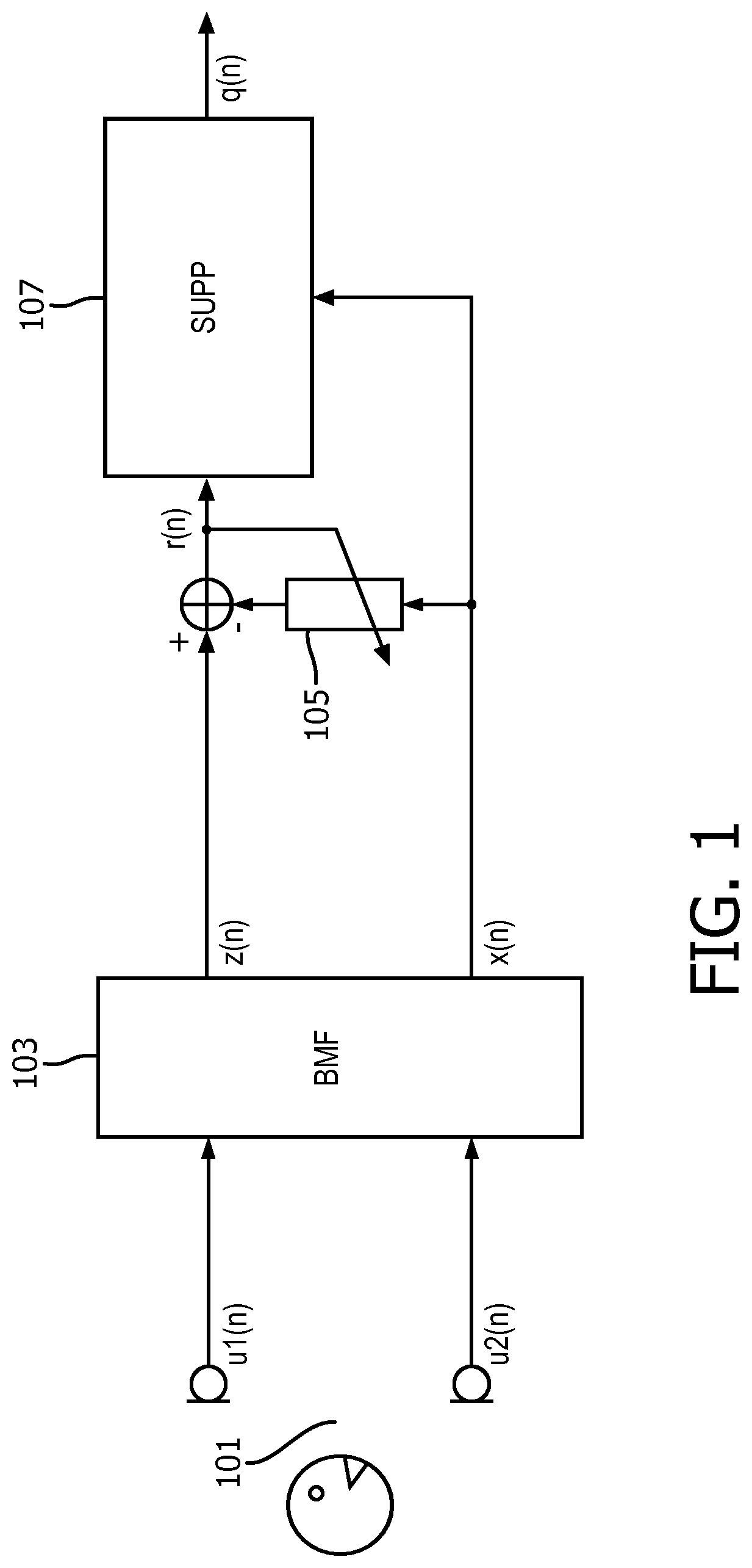
Indeed, although the system of FIG. 1 provides very efficient operation and advantageous performance in many scenarios, it is not optimum in all scenarios.
Indeed, whereas many conventional systems, including the example of FIG. 1, provide very good performance when the desired audio source / speaker is within the reverberation radius of the microphone array, i.e. for applications where the direct energy of the desired audio source is (preferably significantly) stronger than the energy of the reflections of the desired audio source, it tends to provide less optimum results when this is not the case.
In more detail, when dealing with additional diffuse noise and a desired speaker outside the reverberation radius the following problems may occur:The beamformer may often have problems distinguishing between echoes of the desired speech and diffuse background noise, resulting in speech distortion.The adaptive beamformer may converge slower towards the desired speaker.
During the time when the adaptive beam has not yet converged, there will be speech leakage in the reference signal, resulting in speech distortion in case this reference signal is used for non-stationary noise suppression and cancellation.
The problem increases when there are more desired sources that talk after each other.
It may be less efficient for audio sources outside the reverberation radius and may often lead to non-robust solutions in such cases, especially if there is also acoustic diffuse background noise.
Indeed, most algorithms tend to assume that the direct path (and possibly the early reflections) dominate both the later reflections, the reverberation tail, and indeed noise from other sources (including diffuse background noise).
As a consequence, such adaptation approaches tend to be suboptimal in environments where these assumptions are not met, and indeed tend to provide suboptimal performance for many real-life applications.
Indeed, audio capture in general for sources outside the reverberation radius tends to be difficult due to the energy of the direct field from the source to the device being small in comparison to the energy of the reflected speech and the acoustic background noise.
Although multi-beam systems may improve audio capture in such scenarios, the capture will be degraded, or indeed often simply not work, if the adaptation is not reliable.
Current adaptation algorithms tend to be suboptimal and provide relatively poor adaptation for scenarios in which the desired audio source is dominated by late reflections, reverberations, and / or noise, including in particular diffuse noise.
Thus, in many practical applications, the performance of beamforming audio capture systems may be degraded or limited by the adaptation performance.

Method used


Image

  • Audio capture using beamforming
  • Audio capture using beamforming
  • Audio capture using beamforming

Examples


Embodiment Construction

[0101]The following description focuses on embodiments of the invention applicable to a speech capturing audio system based on beamforming but it will be appreciated that the approach is applicable to many other systems and scenarios for audio capturing.

[0102]FIG. 3 illustrates an example of some elements of an audio capturing apparatus in accordance with some embodiments of the invention.

[0103]The audio capturing apparatus comprises a microphone array 301 which comprises a plurality of microphones arranged to capture audio in the environment.

[0104]The microphone array 301 is coupled to a beamformer 303 (typically either directly or via an echo canceller, amplifiers, digital to analog converters etc. as will be well known to the person skilled in the art).

[0105]The beamformer 303 is arranged to combine the signals from the microphone array 301 such that an effective directional audio sensitivity of the microphone array 301 is generated. The beamformer 303 thus generates an output si...


PUM


Abstract

An audio capture apparatus comprises a first beamformer (303) which is arranged to generate a beamformed audio output signal. An adapter (305) adapts beamform parameters of the first beamformer and a detector (307) detects an attack of speech in the beamformed audio output signal. A controller (309) controls the adaptation of the beamform parameters to occur in a predetermined adaptation time interval determined in response to the detection of the attack of speech. The beamformer (303) may generate noise reference signal(s) and the detector (309) may be arranged to detect the attack of speech in response to a comparison of a signal level of the beamformed audio output signal relative to a signal level of the at least one noise reference signal.

Description

FIELD OF THE INVENTION[0001]The invention relates to audio capture using beamforming and in particular.BACKGROUND OF THE INVENTION[0002]Capturing audio, and in particularly speech, has become increasingly important in the last decades. Indeed, capturing speech has become increasingly important for a variety of applications including telecommunication, teleconferencing, gaming, audio user interfaces, etc. However, a problem in many scenarios and applications is that the desired speech source is typically not the only audio source in the environment. Rather, in typical audio environments there are many other audio / noise sources which are being captured by the microphone. One of the critical problems facing many speech capturing applications is that of how to best extract speech in a noisy environment. In order to address this problem a number of different approaches for noise suppression have been proposed.[0003]Indeed, research in e.g. hands-free speech communications systems is a to...

Claims


Application Information

Patent Timeline
IPC IPC(8): H04R3/00G10L21/0208G10L25/87
CPCH04R3/005G10L21/0208G10L2021/02166H04R2430/03G10L25/87G10L25/78
Inventor JANSE, CORNELIS PIETERJANSSEN, RIK JOZEF MARTINUS
Owner KONINKLJIJKE PHILIPS NV
Learn More