Winding group and method for winding paper around a core to make a log

a technology of winding group and core, which is applied in the direction of web handling, article delivery, thin material handling, etc., can solve the problems of limiting the “hold”, destroying the coupling of the core with the “initial edge”, and causing waste, etc., to achieve the effect of being convenient to use, cost-effective and particularly functional

Inactive Publication Date: 2010-07-01
GAMBINI INT
View PDF13 Cites 6 Cited by
  • Summary
  • Abstract
  • Description
  • Claims
  • Application Information

AI Technical Summary

Benefits of technology

[0019]The purpose of the present invention is to make a winding method and group for winding paper around a core to make a log capabl

Problems solved by technology

Such accumulation, as well as making unwanted folds in the paper, damages the coupling of the core with the “initial edge”, the latter coming into contact not always laid out in the i

Method used


Image

  • Winding group and method for winding paper around a core to make a log
  • Winding group and method for winding paper around a core to make a log
  • Winding group and method for winding paper around a core to make a log

Examples


second embodiment

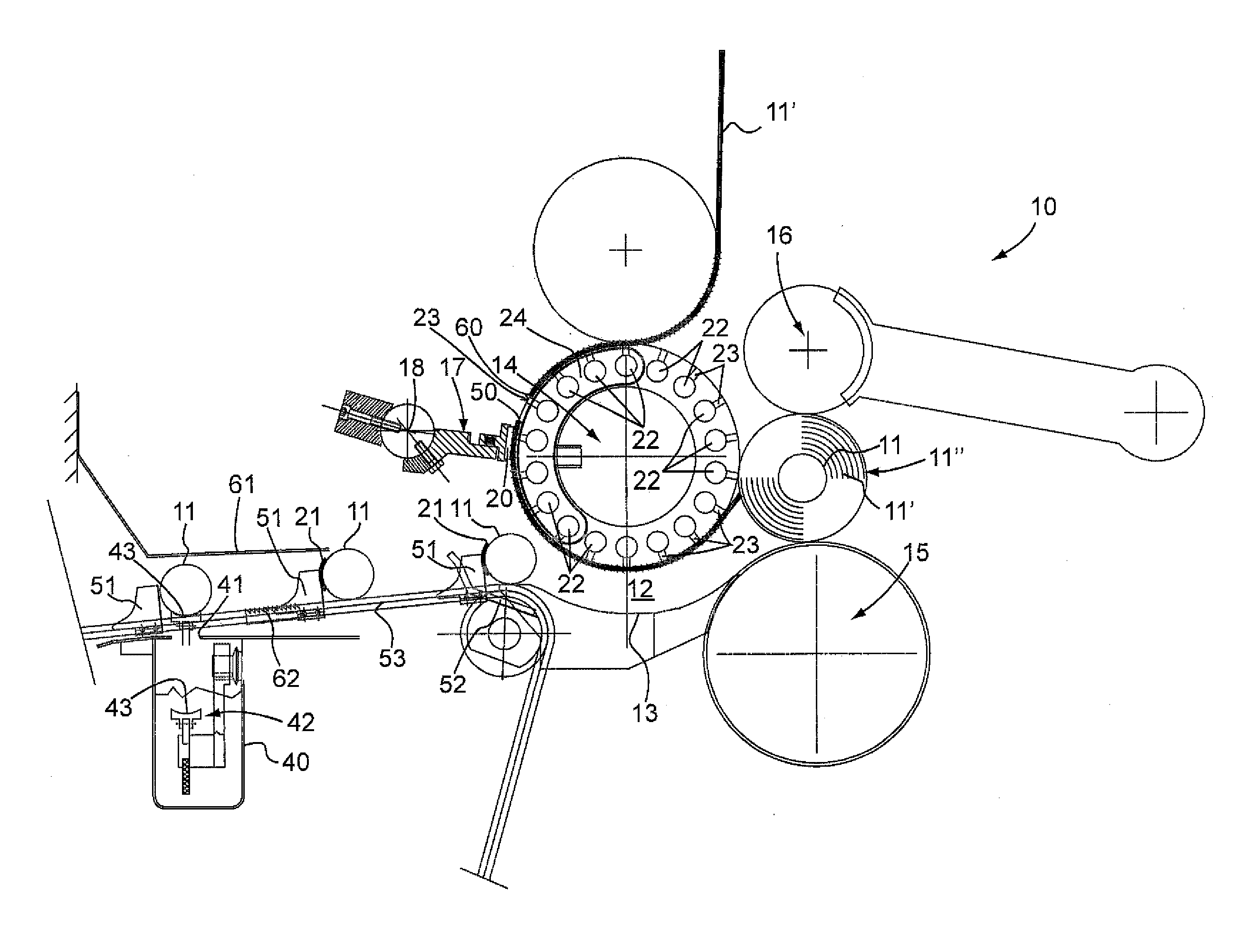
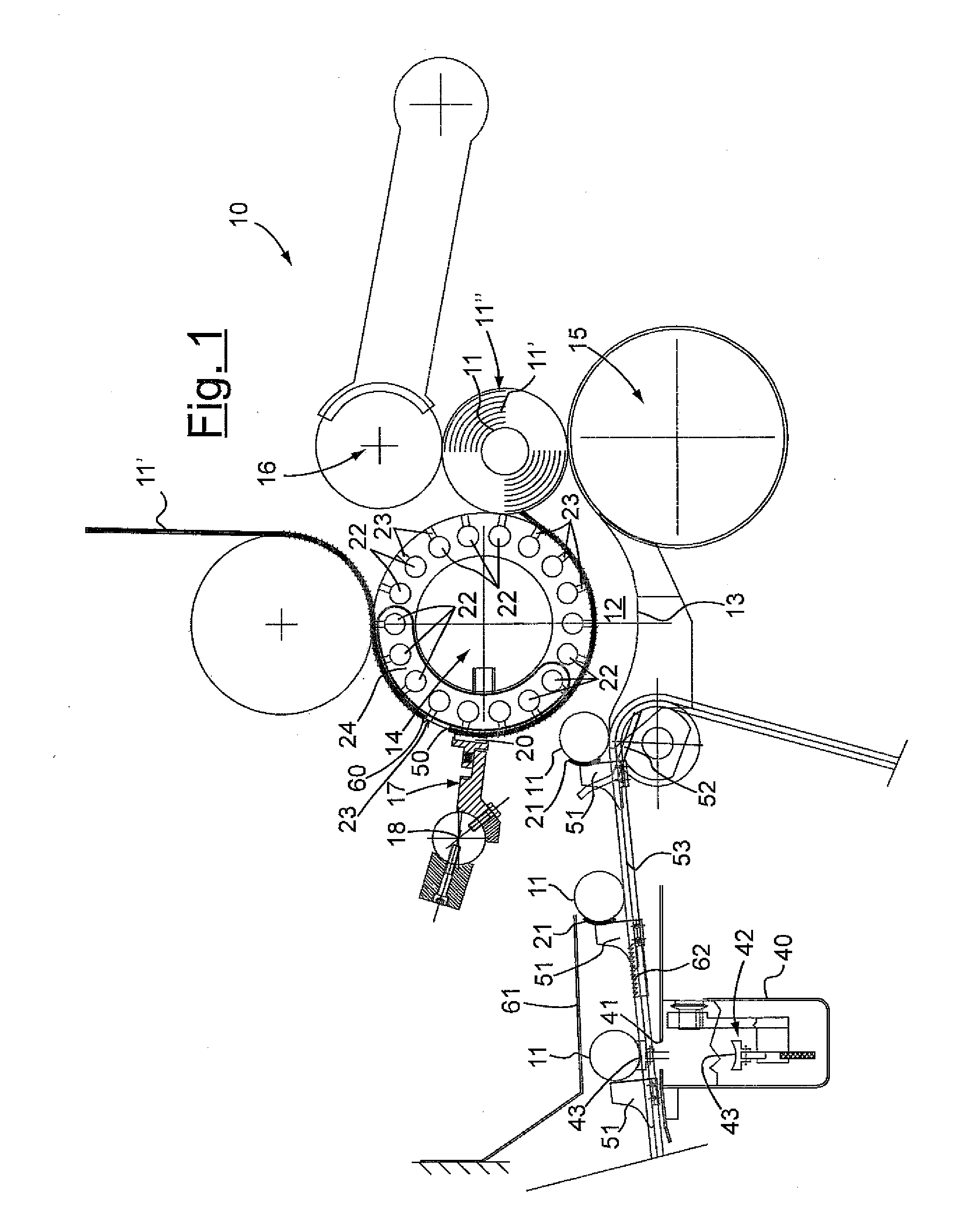
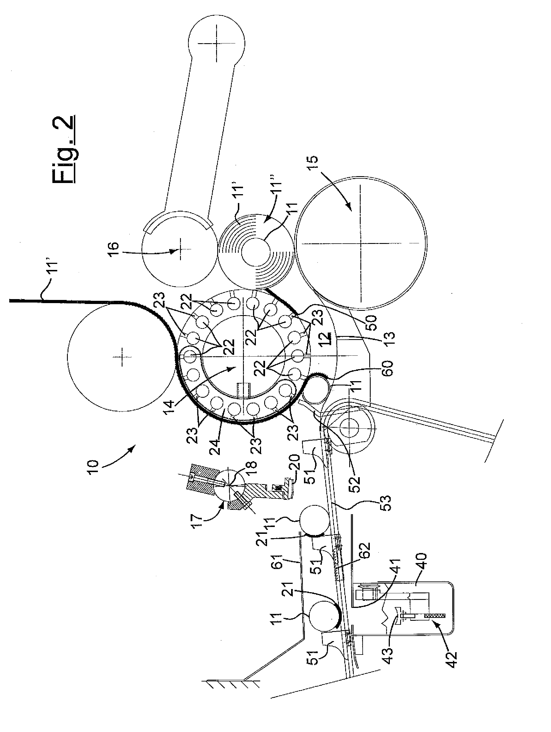
[0047]Thus, in such FIGS. 5-8 the machine 10 comprises a connecting rod 71-crank 72 assembly in which the head of the connecting rod is defined by the guiding support 70 able to slide away from and towards the roller 14, through the effect of the crank 72, on suitable pins 73 or idle rollers. Of course, the movement of such a connecting rod 71-crank 72 assembly is synchronised with the production of the finished logs 11″ in such a way as to take the head 20 of the rod 17, always kept in rotation with respect to the pin 18, in contact with the paper 11′ moving forward on the roller 14 only upon the introduction of a new core 11 into the channel 12.

[0048]According to a preferred embodiment, shown in figures, the cyclic means for tearing the paper 11′ are arranged upstream of the channel 12 and cooperate with means for keeping the paper 11′ adhering around the upper winding roller 14 acting at least upstream of the channel 12.

[0049]Preferably, such means for keeping the paper 11′ act b...

first embodiment

[0058]In a first embodiment shown in FIGS. 1-3 the aforementioned means to cause the winding comprise means for supplying glue 21 to the core 11 arranged upstream of the channel.

[0059]As can be imagined, such glue 21 during the journey of the core 11 in the channel 12 holds the initial edge 60, which proceeds on the roller 14 thanks to the suction means, ensuring safe winding of the paper 11′.

[0060]Alternatively, the means to cause the initial edge 60 to wind on the core 11 introduced into the channel 12 can comprise means for taking the initial edge 60 away from the upper winding roller 14 arranged at the channel 12 substantially downstream of the cyclic means for tearing said paper 11′ and of the suction shoes 24.

[0061]In particular, such means for taking away the initial edge 60 have the purpose of thrusting the initial edge 60 of the paper 11′ towards the lower portion of the channel 12 promoting its firm engagement on the new core 11 that is moving forward in the channel 12 tra...


PUM


Abstract

A winding group for winding paper around a core to make a log comprising in an upstream position, means for transporting and introducing the core into a channel defined at the top by an upper winding roller, supplied from above with the paper directed towards the channel, and at the bottom by a cradle member associated downstream with a lower winding roller, the winding group comprising a third oscillating roller arranged above the lower winding roller, the three rollers cooperating downstream of the channel to wind the paper around the core to make the log, further being provided cyclic means for tearing the paper moving forward on the upper winding roller to identify a final edge and an initial edge as well as means to cause the initial edge to wind on the core introduced into the channel, the cyclic means for tearing the paper comprising a rod member rotating around a pin and provided with a head for cyclic cooperation with the upper winding roller for tearing the paper, wherein the head at least in proximity to the upper winding roller has a greater peripheral speed with respect to that of the upper winding roller to tear the paper upstream of the head.

Description

CROSS-REFERENCE TO RELATED APPLICATIONS[0001]This application claims the benefit of priority from Italian Patent Application No. MI2008A002313, filed Dec. 23, 2008, the contents of which are incorporated herein by reference.FIELD OF THE INVENTION[0002]The present invention refers to an improved winding group and method for winding paper around a core to make a log.BACKGROUND OF THE INVENTION[0003]In common machines for winding paper around a core to make a log, for example for domestic use as toilet paper, paper towel and / or similar, it is currently known to use elements that guide the arriving paper and control its first contact and its winding onto a core in order to make a finished log.[0004]In these machines, usually called rewinders, there are rollers that cooperate to wind the log.[0005]In general, in such known machines there are two fixed rollers that determine the winding of the paper in a log of gradually increasing diameter, whereas a third oscillating roller maintains a ...

Claims


Application Information

Patent Timeline
IPC IPC(8): B65H19/22B65H35/04B65H19/28B65H19/26B65H18/16
CPCB65H19/267
Inventor GAMBINI, GIOVANNI
Owner GAMBINI INT
Why Eureka
Try Eureka