Piezoelectric vibrating pieces, and piezoelectric vibrators and oscillators comprising same
a technology of piezoelectric vibrating and piezoelectric, which is applied in the direction of piezoelectric/electrostrictive/magnetostrictive devices, piezoelectric/electrostrictive/magnetostriction machines, piezoelectric/electrostrictive device details, etc. it can solve the problem of etching anisotropy, unintentional displacement of notch from the center line, and one vibrating arm being more rigid than th
- Summary
- Abstract
- Description
- Claims
- Application Information
AI Technical Summary
Benefits of technology
Problems solved by technology
Method used
Image
Examples
first embodiment
[0037 of Tuning-Fork Type Piezoelectric Vibrating Piece
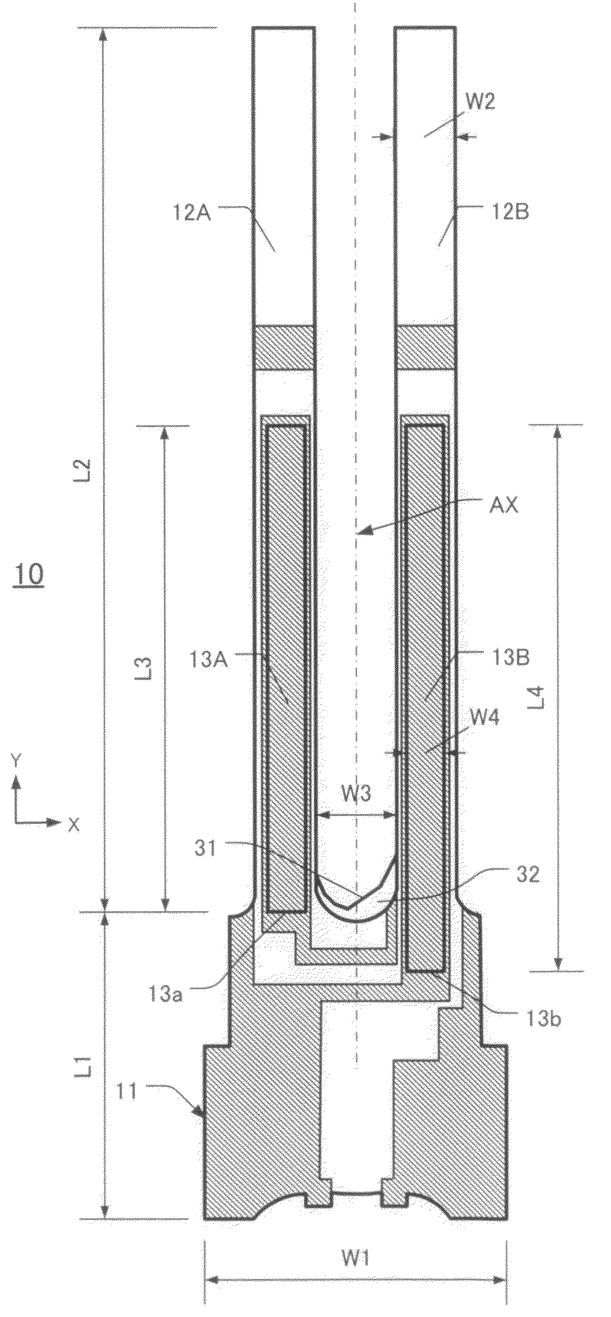
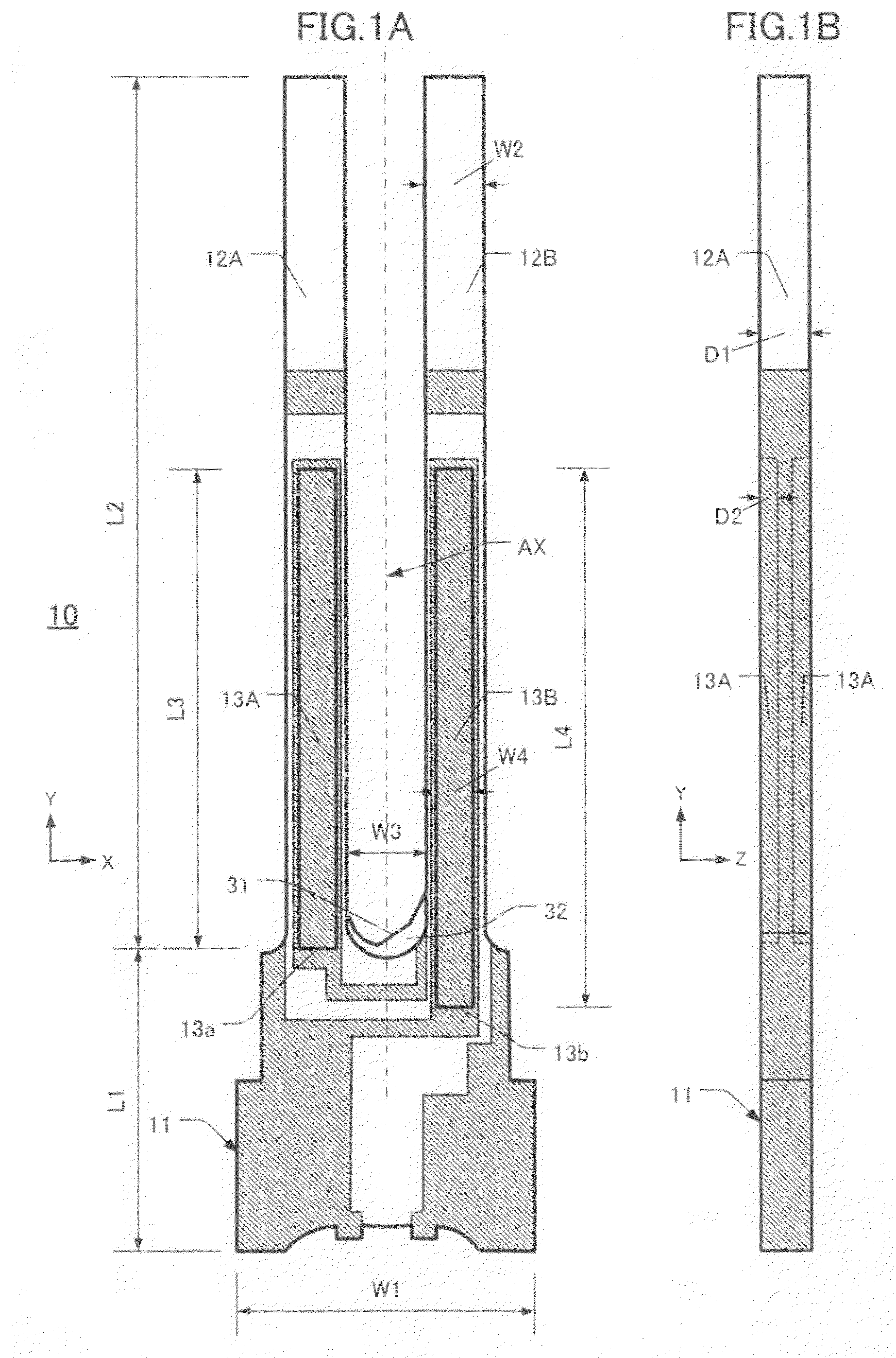
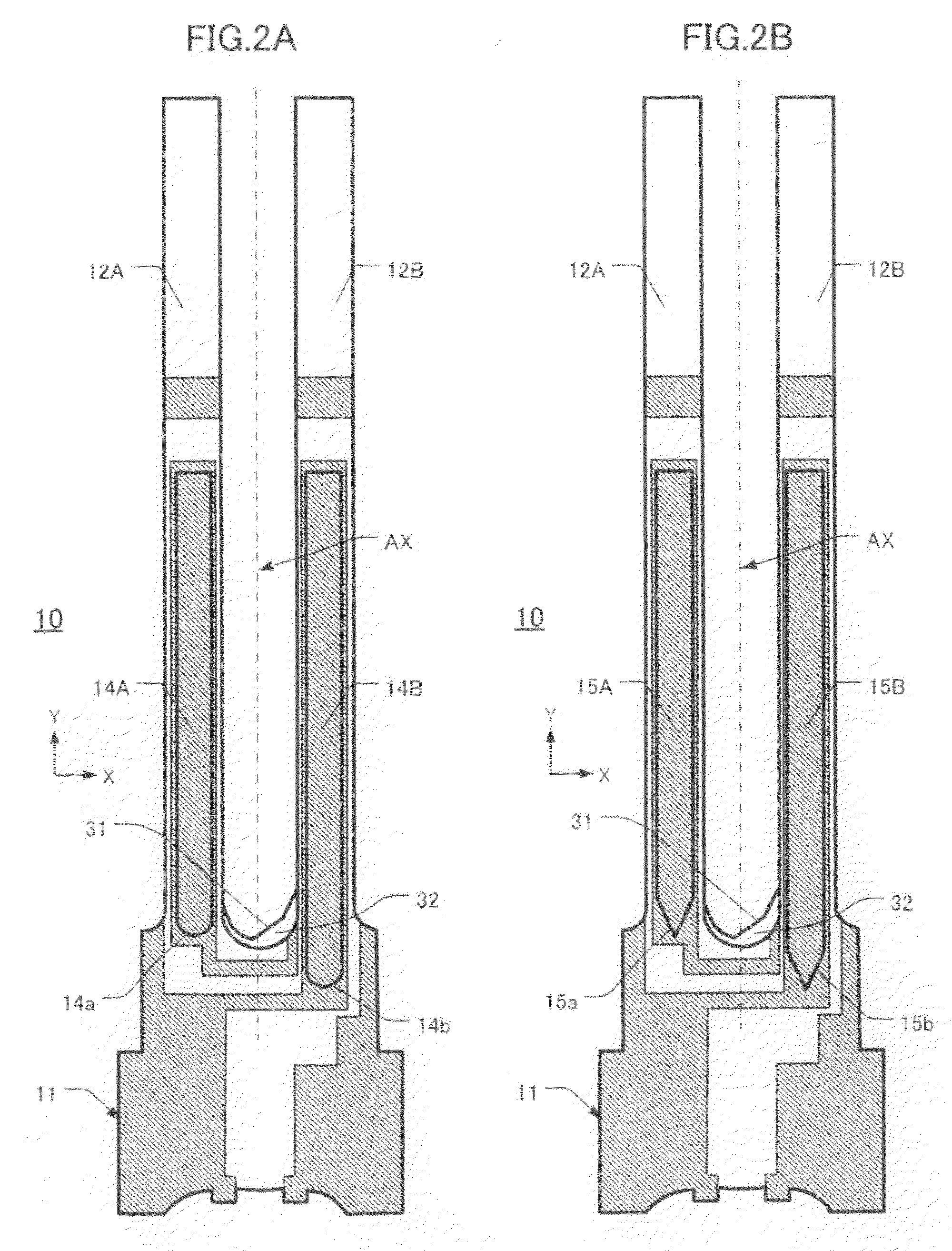
[0038]A tuning-fork type piezoelectric vibrating piece 10 according to the first embodiment is described with reference to FIGS. 1A and 1B and FIGS. 2A and 2B. FIG. 1A is a plan view and FIG. 1B is an orthogonal edge view from the −X-direction side. As shown in FIG. 1A, the tuning-fork type piezoelectric vibrating piece 10 comprises a base portion 11, a first vibrating arm 12A, and a second vibrating arm 12B. The vibrating arms 12A, 12B extend longitudinally (Y-direction) from the base portion 11. The vibrating arms 12A, 12B define first and second grooves 13A, 13B, respectively. The grooves 13A, 13B have different Y-direction lengths and are formed on the upper main surface of the respective vibrating arm 12A, 12B. The proximal portions of the grooves 13A, 13B (i.e., portions nearest the base portion 11) have respective ends 13a, 13b. In the depicted embodiment, these ends 13a, 13b are box-shaped. “Box-shaped” means that the en...
second embodiment
[0044 of Tuning-Fork Type Piezoelectric Vibrating Piece
[0045]This embodiment 10 is described with reference to FIGS. 3A, 3B, and 3C. FIG. 3A is a plan view of a configuration in which the proximal ends of the grooves 16A, 16B are U-shaped 16a and square-shaped 16b, respectively. FIG. 3B is a plan view of a configuration in which the proximal ends of the grooves 17A, 17B are V-shaped 17a and box-shaped 17b, respectively. FIG. 3C is a plan view of a configuration in which the proximal ends of the grooves 18A, 18B are V-shaped 18a and U-shaped 18b. Compared to the first embodiment, the only differences in the second embodiment are the lengths of the grooves and the shapes of the proximal ends of the grooves. Hence, further description of elements that are the same in both embodiments is omitted. Also, components in both embodiments that are similar have the same respective reference numerals.
[0046]In FIG. 3A the crotch 31 is more etched adjacent the first vibrating arm 16A compared to ...
third embodiment
[0048 of Tuning-Fork Type Piezoelectric Vibrating Piece
[0049]This embodiment 10 of a tuning-fork type piezoelectric vibrating piece is described with reference to FIGS. 4A and 4B. FIGS. 4A and 4B are plan views of two configurations of a tuning-fork type piezoelectric vibrating piece 10 according to this embodiment. In FIG. 4A the proximal end of the groove 19A has a unilaterally curved profile. As a result, the proximal end 19a of the vibrating arm 12A is linearly asymmetrical about the center-line BX (which is the longitudinal center-line of the groove 19A in the Y-direction). The proximal end 19b of the second vibrating arm 12B has the same shape as item 19a.
[0050]Turning now to FIG. 4B, the proximal ends 20a, 20b of the grooves 20A, 20B both have a unilateral stepped (stair-like) profile. As a result, each proximal end 20a, 20b is linearly asymmetrical about the respective center-line BX. Since only the respective shapes of the proximal ends of the grooves in the third embodime...
PUM
 Abstract
Description
Claims
Application Information
 - R&D
- Intellectual Property
- Life Sciences
- Materials
- Tech Scout
- Unparalleled Data Quality
- Higher Quality Content
- 60% Fewer Hallucinations
Browse by: Latest US Patents, China's latest patents, Technical Efficacy Thesaurus, Application Domain, Technology Topic, Popular Technical Reports.
© 2025 PatSnap. All rights reserved.Legal|Privacy policy|Modern Slavery Act Transparency Statement|Sitemap|About US| Contact US: help@patsnap.com


