Piezoelectric vibrating pieces, and piezoelectric vibrators and oscillators comprising same

a technology of piezoelectric vibrators and oscillators, which is applied in the direction of piezoelectric/electrostrictive/magnetostrictive devices, piezoelectric/electrostriction/magnetostriction machines, impedence networks, etc. it can solve the problem of etching anisotropy, unintentional displacement of notch lines, and rigidity of vibrating arms. to achieve the effect of balanced rigidity of vibrating arms

Inactive Publication Date: 2011-12-13
NIHON DEMPA KOGYO CO LTD
View PDF10 Cites 2 Cited by
  • Summary
  • Abstract
  • Description
  • Claims
  • Application Information

AI Technical Summary

Benefits of technology

[0012]According to a first aspect of the invention, piezoelectric vibrating pieces are provided. An embodiment of such a piezoelectric vibrating piece comprises a base portion and first and second vibrating arms. The first and second vibrating arms extend in a designated longitudinal direction (e.g., Y-direction) from the base portion. Each vibrating arm has first and second main surfaces. A first groove is defined in the first main surface and a second groove is defined in the second main surface of each vibrating arm. Each groove extends in the longitudinal direction, wherein at least the first grooves are not symmetrical with each other about a center-line extending in the longitudinal direction between the first and second vibrating arms. By adjusting the shapes of at least the first grooves in this manner, any unbalanced rigidity of the vibrating arms [caused by, e.g., the presence of a deformed portion or other etching anisotropy situated in the region (e.g., crotch region) between the vibrating arms] can be prevented or rectified.
[0013]In certain embodiments, whereas each first groove has a proximal end and a distal end, the proximal ends are nearer the base portion than the distal ends, and the proximal ends have similar shapes but different coordinates in the longitudinal direction. According to this configuration, the particular vibrating arm having more rigidity than the other is provided with a longer groove at least on the first main surface thereof. Thus, the rigidity of the first and second vibrating arms can be balanced.
[0015]In other embodiments, the proximal ends of at least the first grooves are nearer the base portion than the distal ends, wherein the proximal ends have different shapes. Thus, the particular vibrating arm having greater rigidity than the other arm can be provided with, for example, a larger proximal region of the groove on at least the first main surface. Thus, the rigidity of the vibrating arms can be balanced.
[0016]Various combinations of shapes of the proximal ends are possible. As a first example, the proximal end of the first groove in the first vibrating arm can be U-shaped, while the proximal end of the first groove in the second vibrating arm is box-shaped. The box shape can provide a slightly larger proximal end than the U-shape. As a second example, the proximal end of the first groove in the first vibrating arm can be V-shaped, while the proximal end of the first groove in the second vibrating arm is box-shaped. The box shape provides a slightly larger proximal end than the V-shape. As a third example, the proximal end of the first groove in the first vibrating arm can be V-shaped, while the proximal end of the first groove in the second vibrating arm is U-shaped. The U-shape provides a slightly larger proximal end than the V-shape. These configurations provide ways to balance the rigidity of the vibrating arms.
[0021]The various aspects summarized above provide piezoelectric vibrating pieces in which the rigidity of the vibrating arms can be balanced, and the adverse effects of any deformities (especially asymmetric deformities) between the vibrating arms caused by etching anisotropies or the like can be reduced by adjusting the length and shapes of the grooves formed on the vibrating arms. Thus, a higher proportion of vibrators and oscillators produced on an assembly line exhibit oscillation frequencies that are within specification.

Problems solved by technology

Such an asymmetric or misdirected notch can cause one vibrating arm to be more rigid than the other vibrating arm.
One cause of a notch unintentionally displaced from the center line is an etching anisotropy arising during a wet-etching process for forming the vibrating arms and base.
For example, the deformity can cause the notch to be displaced on the center line or to be misoriented relative to the longitudinal direction, which changes the rigidity of one vibrating arm relative to the rigidity of the other.
Consequently, the oscillation of the vibrating arms becomes unbalanced.
In view of the high degree of miniaturization of the vibrating pieces, these specifications place extreme demands on the wet-etching process used for forming the crotch, which can make it difficult to produce, especially on a consistent basis, oscillators exhibiting balanced oscillations of the vibrating arms.
The narrower space is more difficult to wet-etch evenly, which increases the probability of producing defective product.
A relatively larger deformed region can have a more pronounced adverse effect on oscillation balance.

Method used


Image

  • Piezoelectric vibrating pieces, and piezoelectric vibrators and oscillators comprising same
  • Piezoelectric vibrating pieces, and piezoelectric vibrators and oscillators comprising same
  • Piezoelectric vibrating pieces, and piezoelectric vibrators and oscillators comprising same

Examples


first embodiment

of Tuning-Fork Type Piezoelectric Vibrating Piece

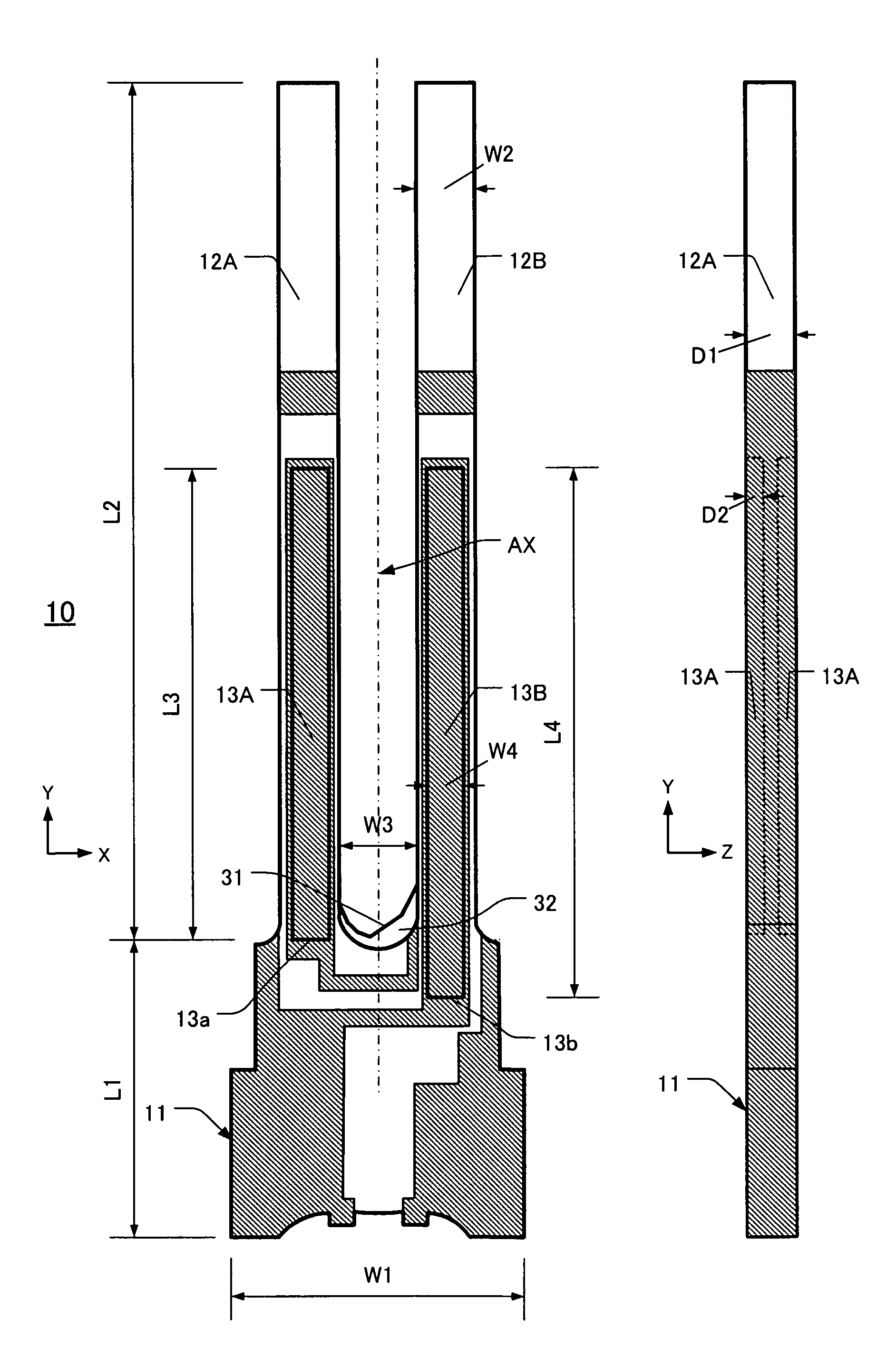
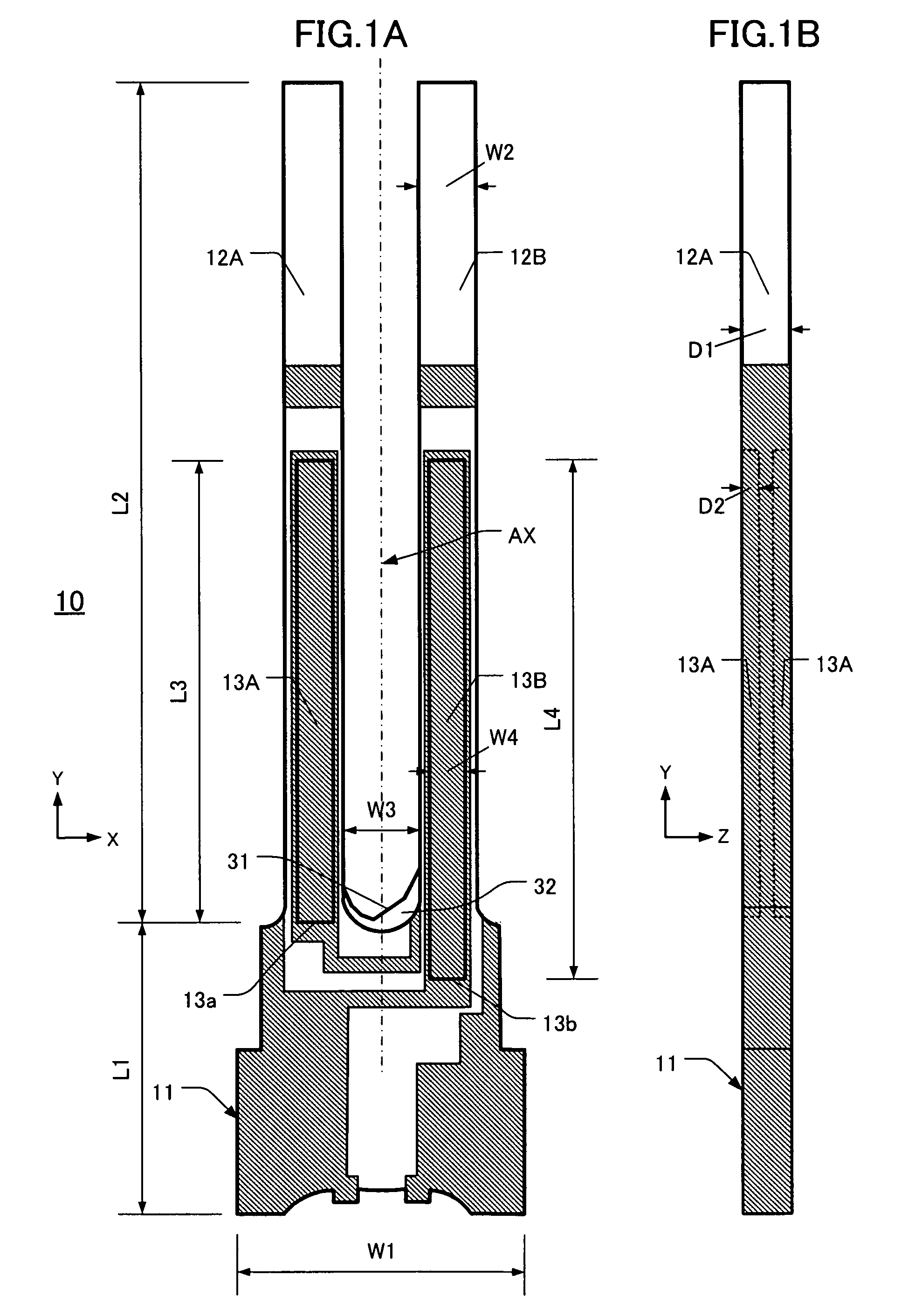
[0038]A tuning-fork type piezoelectric vibrating piece 10 according to the first embodiment is described with reference to FIGS. 1A and 1B and FIGS. 2A and 2B. FIG. 1A is a plan view and FIG. 1B is an orthogonal edge view from the −X-direction side. As shown in FIG. 1A, the tuning-fork type piezoelectric vibrating piece 10 comprises a base portion 11, a first vibrating arm 12A, and a second vibrating arm 12B. The vibrating arms 12A, 12B extend longitudinally (Y-direction) from the base portion 11. The vibrating arms 12A, 12B define first and second grooves 13A, 13B, respectively. The grooves 13A, 13B have different Y-direction lengths and are formed on the upper main surface of the respective vibrating arm 12A, 12B. The proximal portions of the grooves 13A, 13B (i.e., portions nearest the base portion 11) have respective ends 13a, 13b. In the depicted embodiment, these ends 13a, 13b are box-shaped. “Box-shaped” means that the ends ext...

second embodiment

of Tuning-Fork Type Piezoelectric Vibrating Piece

[0046]This embodiment 10 is described with reference to FIGS. 3A, 3B, and 3C. FIG. 3A is a plan view of a configuration in which the proximal ends of the grooves 16A, 16B are U-shaped 16a and square-shaped 16b, respectively. FIG. 3B is a plan view of a configuration in which the proximal ends of the grooves 17A, 17B are V-shaped 17a and box-shaped 17b, respectively. FIG. 3C is a plan view of a configuration in which the proximal ends of the grooves 18A, 18B are V-shaped 18a and U-shaped 18b. Compared to the first embodiment, the only differences in the second embodiment are the lengths of the grooves and the shapes of the proximal ends of the grooves. Hence, further description of elements that are the same in both embodiments is omitted. Also, components in both embodiments that are similar have the same respective reference numerals.

[0047]In FIG. 3A the crotch 31 is more etched adjacent the first vibrating arm 16A compared to adjace...

third embodiment

of Tuning-Fork Type Piezoelectric Vibrating Piece

[0049]This embodiment 10 of a tuning-fork type piezoelectric vibrating piece is described with reference to FIGS. 4A and 4B. FIGS. 4A and 4B are plan views of two configurations of a tuning-fork type piezoelectric vibrating piece 10 according to this embodiment. In FIG. 4A the proximal end of the groove 19A has a unilaterally curved profile. As a result, the proximal end 19a of the vibrating arm 12A is linearly asymmetrical about the center-line BX (which is the longitudinal center-line of the groove 19A in the Y-direction). The proximal end 19b of the second vibrating arm 12B has the same shape as item 19a.

[0050]Turning now to FIG. 4B, the proximal ends 20a, 20b of the grooves 20A, 20B both have a unilateral stepped (stair-like) profile. As a result, each proximal end 20a, 20b is linearly asymmetrical about the respective center-line BX. Since only the respective shapes of the proximal ends of the grooves in the third embodiment are...


PUM


Abstract

Piezoelectric vibrating pieces are disclosed that include a base portion and first and second vibrating arms extending in a longitudinal direction from the base portion. Each vibrating arm has first and second main surfaces, a first groove on the first main surface, and a second groove on the second main surface. The grooves extend in the longitudinal. By adjusting the length and shapes of at least the first grooves relative to each other, the rigidity of the vibrating arms can be balanced and adverse effects of deformed regions between the vibrating arms caused by anomalous etching can be reduced.

Description

CROSS-REFERENCE TO RELATED APPLICATION[0001]This application claims priority to and the benefit of Japan Patent Application No. 2008-330206, filed on Dec. 25, 2008, in the Japan Patent Office, the disclosure of which is incorporated herein by reference in its entirety.FIELD[0002]This disclosure pertains to, inter alia, piezoelectric vibrating pieces of which grooves are formed on the vibrating arms, and to piezoelectric vibrators and oscillators comprising such a piezoelectric vibrating piece.DESCRIPTION OF THE RELATED ART[0003]Piezoelectric oscillators including a piezoelectric vibrating piece are used in many small data devices, such as HDDs (Hard Disc Drives), mobile computers, IC cards, and clock sources for mobile phones. A conventional “tuning-fork type piezoelectric vibrating piece” comprises a roughly rectangularly-shaped base portion from which a pair of vibrating arms extend. Electrical energization of the vibrating arms causes them to vibrate relative to the base portion,...

Claims


Application Information

Patent Timeline
Patent Type & Authority Patents(United States)
IPC IPC(8): H01L41/08
CPCH01L41/1132H03H9/0547H03H9/1021H03H9/21H10N30/302
Inventor KAWANISHI, SHINGO
Owner NIHON DEMPA KOGYO CO LTD
Why Eureka
Try Eureka