Lighting device with switchable light sources

a technology of switchable light source and light producing device, which is applied in the direction of lighting and heating apparatus, process and machine control, instruments, etc., can solve the problems of various limitations of conventional lighting device, and achieve the effect of preventing the rotation of the bezel

Active Publication Date: 2010-07-01
SUREFIRE LLC
View PDF26 Cites 34 Cited by
  • Summary
  • Abstract
  • Description
  • Claims
  • Application Information

AI Technical Summary

Benefits of technology

[0008]In one embodiment, a lighting device includes a plurality of light sources, a body, a head, and one or more controls adapted to adjust operation of the light sources. The body includes a housing. The head includes a bezel adapted to rotate relative to the body to select between at least a first one of the light sources and a second one of the light sources. The head also includes a lens adapted to rotate eccentrically relative to a centerline of the head in response to rotation of the bezel. The lens includes a light inlet adapted to be selectively positioned over the first light source, the second light source, or neither of the light sources as the lens rotates eccentrically relative to the centerline of the head.
[0009]In another embodiment, a method of operating a lighting device is provided. The lighting device includes a plurality of light sources, a head including a bezel, a lens, and a lock ring, a body including a housing, and one or more controls adapted to adjust operation of the light sources. The method includes urging the lock ring from a locked position to an unlocked position. The lock ring is adapted to prevent rotation of the bezel while the lock ring is in the locked position and permit rotation of the bezel while the lock ring is in the unlocked position. The method also includes rotating the bezel to select a first one of the light sources or a second one of the light sources. The rotating causes the lens to rotate eccentrically relative to a centerline of the head. The lens includes a light inlet adapted to be selectively positioned over the first light source, the second light source, or neither of the light sources as the lens rotates eccentrically relative to the centerline of the head. The method also includes returning the lock ring to the locked position.
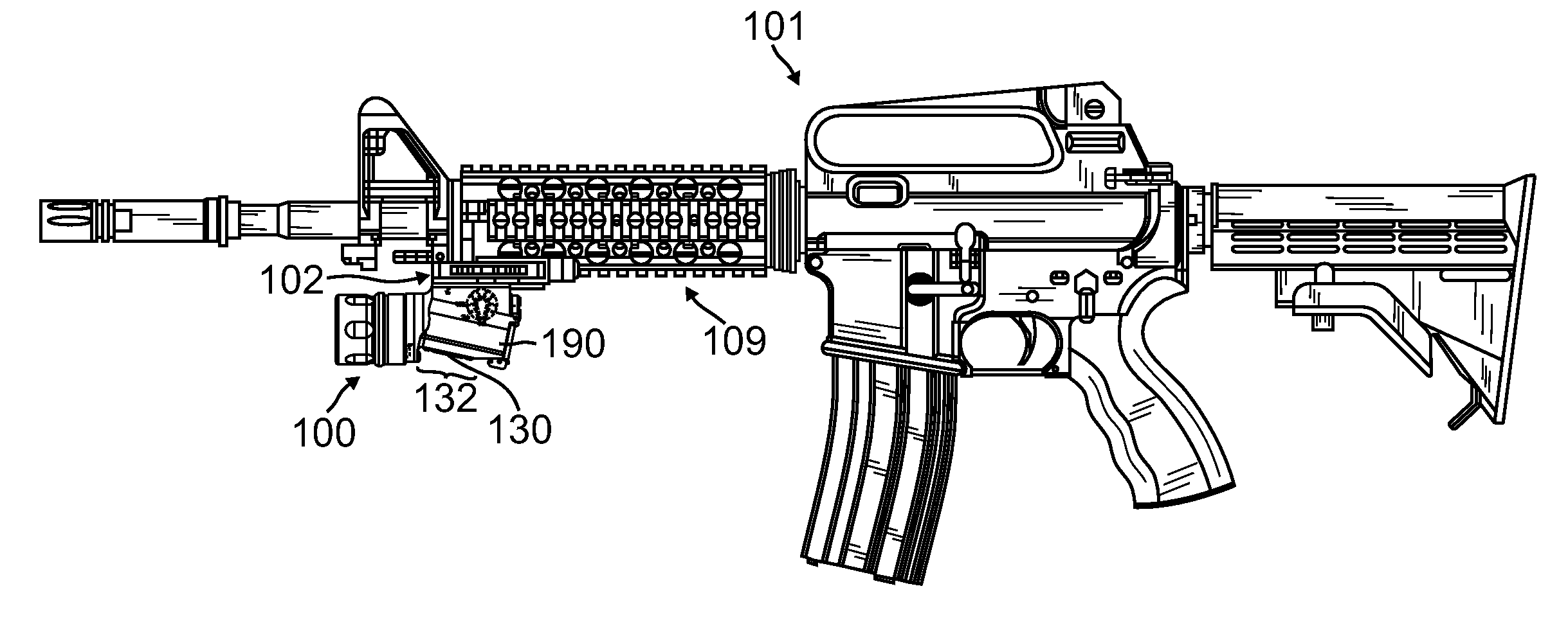
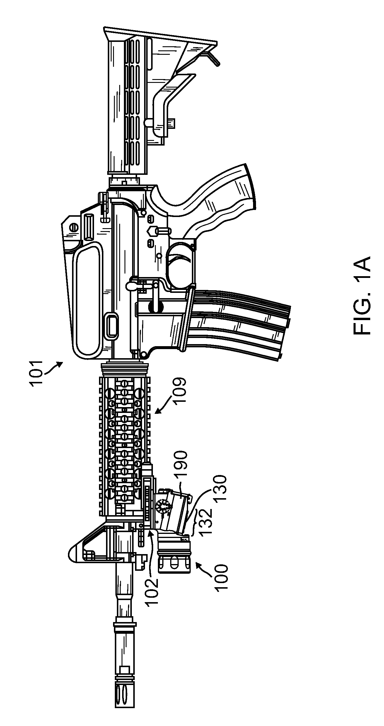
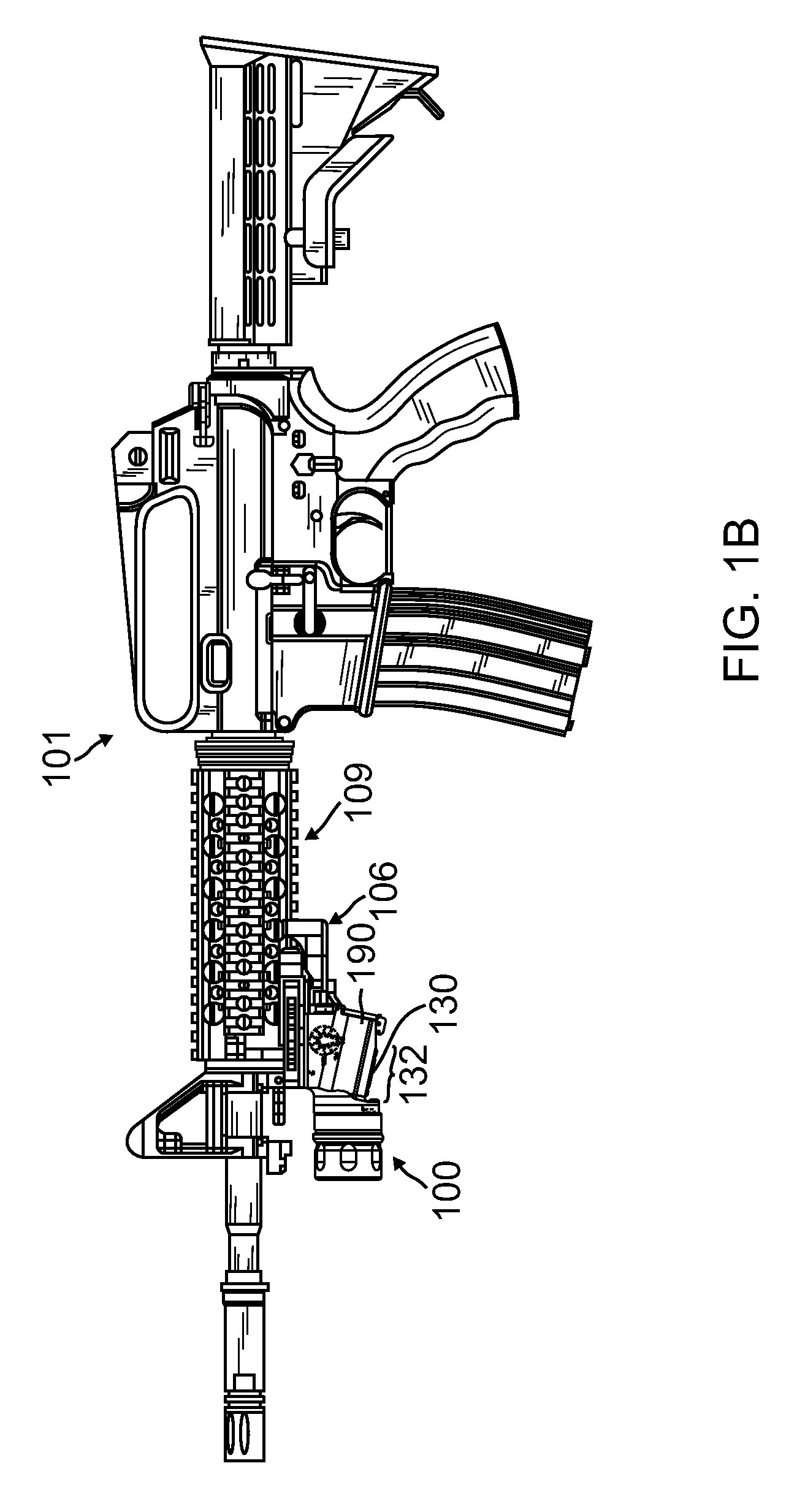
[0010]In another embodiment, a lighting system includes a lighting device. The lighting device includes a plurality of light sources, a body, a head, and one or more controls adapted to adjust operation of the light sources. The body includes a housing, a connector, and a mounting surface. The head includes a bezel adapted to rotate relative to the body to select between at least a first one of the light sources and a second one of the light sources. The head also includes a lens adapted to rotate eccentrically relative to a centerline of the head in response to rotation of the bezel. The lens includes a light inlet adapted to be selectively positioned over the first light source, the second light source, or neither of the light sources as the lens rotates eccentrically relative to the centerline of the head. The lighting system also includes a remote switch. The connector is adapted to receive the remote switch to control at least one of the light sources. The lighting system also includes a rail clamp mount. The mounting surface is adapted to engage with the rail clamp mount to attach the lighting device to a weapon.
[0011]In another embodiment, a lighting device includes a plurality of light sources, a body, a head, and one or more controls adapted to adjust operation of the light sources. The body includes a housing. The head includes a bezel adapted to rotate relative to the body to select between at least a first one of the light sources and a second one of the light sources. The head also includes a reflector adapted to rotate eccentrically relative to a centerline of the head in response to rotation of the bezel. The reflector comprises a light inlet adapted to be selectively positioned over the first light source, the second light source, or neither of the light sources as the reflector rotates eccentrically relative to the centerline of the head.
[0012]The scope of the invention is defined by the claims, which are incorporated into this section by reference. A more complete understanding of embodiments of the present invention will be afforded to those skilled in the art, as well as a realization of additional advantages thereof, by a consideration of the following detailed description of one or more embodiments. Reference will be made to the appended sheets of drawings that will first be described briefly.

Problems solved by technology

Unfortunately, such conventional lighting devices have various limitations.

Method used


Image

  • Lighting device with switchable light sources
  • Lighting device with switchable light sources
  • Lighting device with switchable light sources

Examples


Embodiment Construction

[0027]In accordance with various embodiments provided herein, a lighting device may be implemented to selectively provide various types of light, such as light of different wavelengths, in response to user-actuated controls. For example, in one embodiment, such a lighting device may be a weapon-mountable lighting device providing convenient access to user controls for selectively configuring (e.g., adjusting) the operation of the lighting device. For example, such user controls may be used to adjust the switching of light sources as well as the brightness and wavelengths of light emitted by such light sources. In one embodiment, such light sources may be implemented with a plurality of light emitting diodes (LEDs) which may be selectively activated and selectively dimmed to provide light of different wavelengths. Light sources other than LEDs may be used in other embodiments.

[0028]Such a lighting device may be used in any desired combination with the various features identified in t...


PUM


Abstract

Various lighting device implementations and related methods may be used to selectively provide various types of light in response to user-actuated controls. In one example, a lighting device includes a plurality of light sources, a body, a head, and one or more controls adapted to adjust operation of the light sources. The body includes a housing. The head includes a bezel adapted to rotate relative to the body to select between at least a first one of the light sources and a second one of the light sources. The head also includes a lens adapted to rotate eccentrically relative to a centerline of the head in response to rotation of the bezel. The lens includes a light inlet adapted to be selectively positioned over the first light source, the second light source, or neither of the light sources as the lens rotates eccentrically relative to the centerline of the head.

Description

CROSS-REFERENCE TO RELATED APPLICATIONS[0001]This application is a continuation-in-part application of U.S. patent application Ser. No. 12 / 248,704 entitled “SWITCHABLE LIGHT SOURCES” filed Oct. 9, 2008, which is hereby incorporated by reference in its entirety. This application claims the benefit of U.S. Provisional Patent Application Ser. No. 61 / 295,067 entitled, “LIGHTING DEVICE WITH SWITCHABLE LIGHT SOURCES” filed Jan. 14, 2010, which is hereby incorporated by reference in its entirety.BACKGROUND[0002]1. Field of the Invention[0003]The present invention generally relates to light producing devices and more particularly relates to light producing devices with switchable light sources.[0004]2. Related Art[0005]As is well known, light producing devices are typically configured to perform only a single function, namely, to illuminate areas of interest. For example, conventional lighting devices are typically implemented with mechanical and electrical structures directed to performing...

Claims


Application Information

Patent Timeline
Patent Type & Authority Applications(United States)
IPC IPC(8): H05B37/02F21V1/00F41G1/34
CPCF21L4/025F21V23/0414F41G1/35F41G11/003F21V29/20F21V29/70
Inventor MATTHEWS, JOHN W.PICCIOTTA, MICHAEL D.WELLS, WILLIAM
Owner SUREFIRE LLC
Why Eureka
Try Eureka