Method of managing multiple vehicle antennas
a technology of vehicle antenna and wireless communication, applied in the field of wireless communication with a vehicle, can solve the problems of impeding the telematics device and circumventing the vehicle tracking
- Summary
- Abstract
- Description
- Claims
- Application Information
AI Technical Summary
Benefits of technology
Problems solved by technology
Method used
Image
Examples
first embodiment
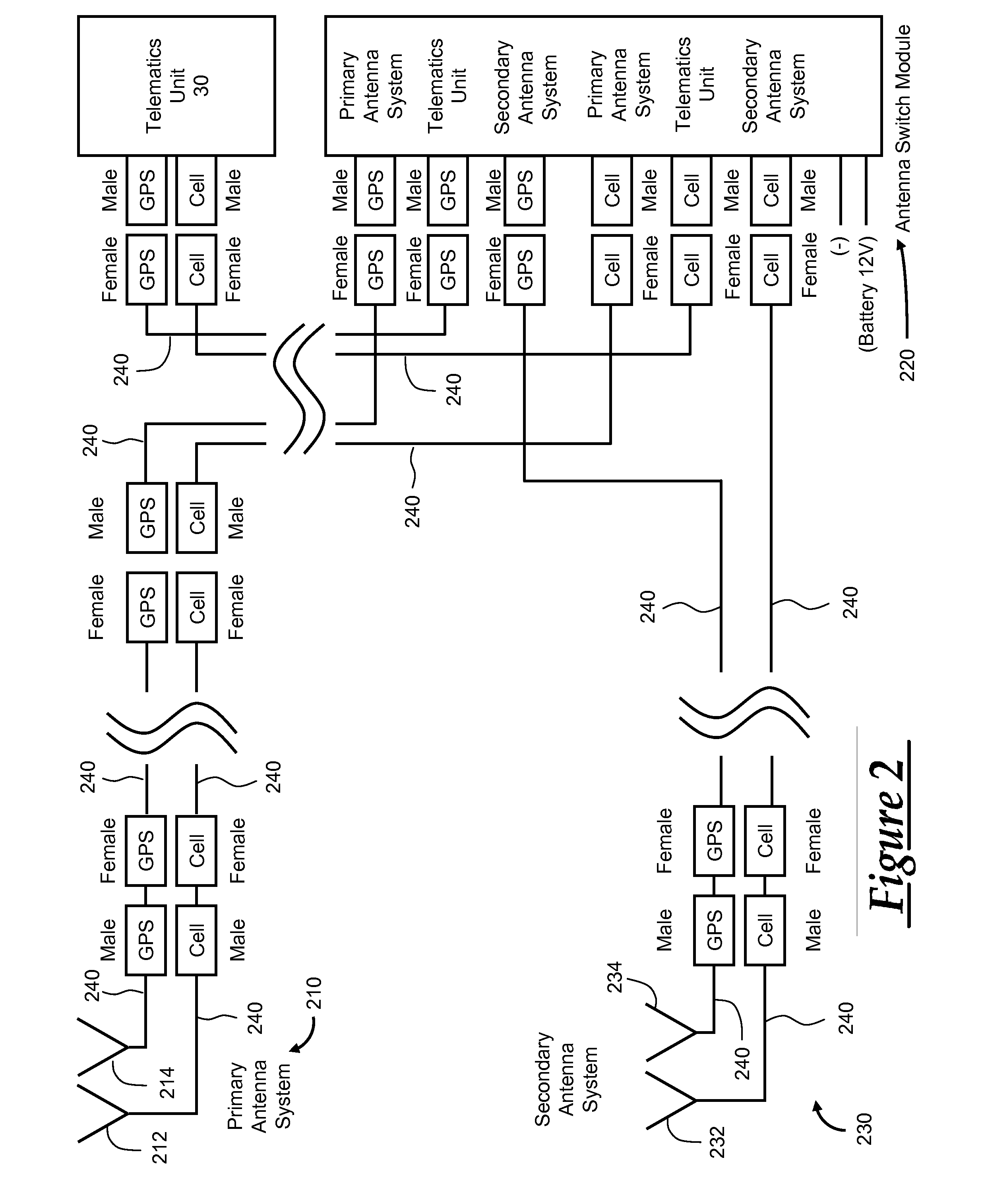
[0037]Shown in FIG. 3 is a first embodiment for carrying out a first method of switching between antenna systems. A system 300 for implementing the method is shown. The system 300 in FIG. 3 can be referred to as the Thru-Loss system. The system 300 includes a primary antenna system 310, a secondary antenna system 330, a secondary directional coupler 320, an antenna control switch 340, a primary directional coupler 350, an amplifier 360, a detector 370, a controller 380, a signal generator 390, and the telematics unit 30. These elements of system 300 are linked via data cables 395 that are similar to data cables 240 shown in FIG. 2 and described above.
[0038]In system 300, the signal generator 390 generates an RF current that flows through data cables 395 to the secondary directional coupler 320. The coupler 320 transfers a portion of the RF current to the secondary antenna system 330 through the data cable 395 linking the secondary directional coupler 320 and the secondary antenna sy...
second embodiment
[0040]Shown in FIG. 4 is a second embodiment for carrying out a second method of switching between antenna systems. A system 400 for implementing the method is shown. The system in FIG. 4 will be referred to as the Continuity system. The system 400 includes a primary antenna system 410, a secondary antenna system 430, a primary sampler 420, an antenna controller 440, a detector 450, a comparator 460, a controller 470, and the telematics unit 30. These elements of system 400 are linked via data cables 490 that are similar to data cables 240 shown in FIG. 2 and described above.
[0041]The primary antenna system 410 and the secondary antenna system 430 each contain a status reference element that can be used to determine the condition of both the primary antenna system 410 and the secondary antenna system 430. Examples of the status reference element include a pull up resistor or a pull down resistor that adds a dc signal or other sample information onto signals conducted from one or bot...
third embodiment
[0043]Shown in FIG. 5 is a third embodiment for carrying out a third method of switching between antenna systems. A system 500 for implementing the method is shown. The system in FIG. 5 will be referred to as the Return Loss system. The system 500 includes a primary antenna system 510, an antenna controller 520, a secondary antenna system 530, a dual-direction coupler 540, a dual detector 550, a controller 560, and the telematics unit 30. These elements of system 500 are linked via data cables 590 that are similar to data cables 240 shown in FIG. 2 and described above.
[0044]In system 500, the telematics unit 30 transmits an RF current to the dual-directional coupler 540. The dual-directional coupler 540 can provide samples of RF power from both an RF power transmitted to the antenna controller 520 and power reflected back from the primary antenna system 510. Samples of both the RF power transmitted to the antenna controller 520 and the RF power reflected back from the primary antenn...
PUM
 Abstract
Description
Claims
Application Information
 - R&D
- Intellectual Property
- Life Sciences
- Materials
- Tech Scout
- Unparalleled Data Quality
- Higher Quality Content
- 60% Fewer Hallucinations
Browse by: Latest US Patents, China's latest patents, Technical Efficacy Thesaurus, Application Domain, Technology Topic, Popular Technical Reports.
© 2025 PatSnap. All rights reserved.Legal|Privacy policy|Modern Slavery Act Transparency Statement|Sitemap|About US| Contact US: help@patsnap.com


