
Stereoscopic display apparatus and display method

Active Publication Date: 2010-07-01
IND TECH RES INST
View PDF4 Cites 8 Cited by
  • Summary
  • Abstract
  • Description
  • Claims
  • Application Information

AI Technical Summary

Benefits of technology

[0018]In the present disclosure, the light-emitting regions of the dynamic backlight module or the transmissive regions of the tracking panel are synchronally controlled according to image-updating condition of the display panel. Accordingly, cross talk phenomenon of the stereoscopic display apparatus can be improved significantly.

Problems solved by technology

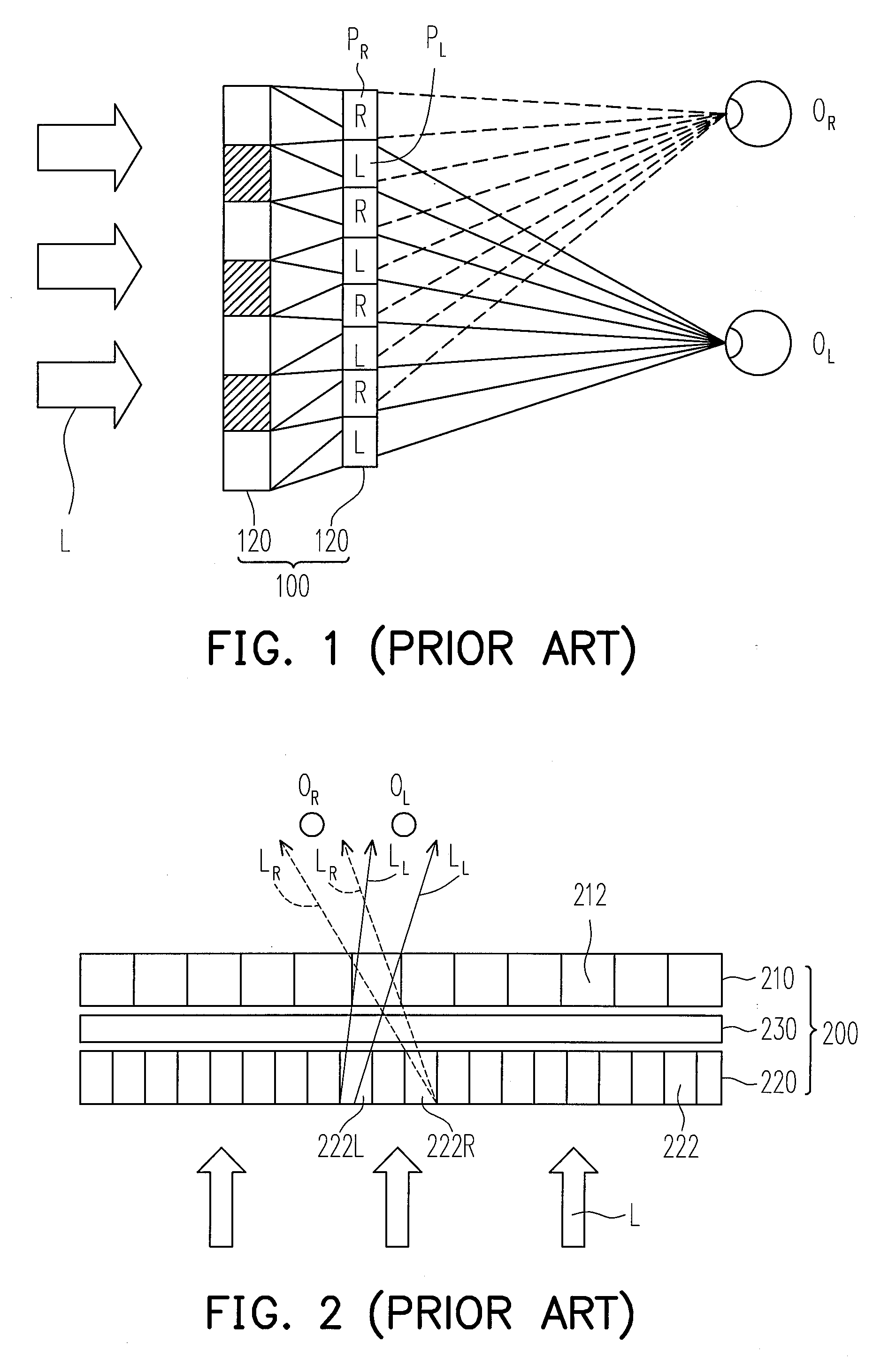
The glasses-stereoscopic type three-dimensional display technology has been developed to be mature and widely applied to some special fields such as military simulation or large-scale recreations, but the glasses-stereoscopic type three-dimensional display technology is difficult to be popularized due to its inconvenient and discomfort features.

Method used


Image

  • Stereoscopic display apparatus and display method
  • Stereoscopic display apparatus and display method
  • Stereoscopic display apparatus and display method

Examples


first embodiment

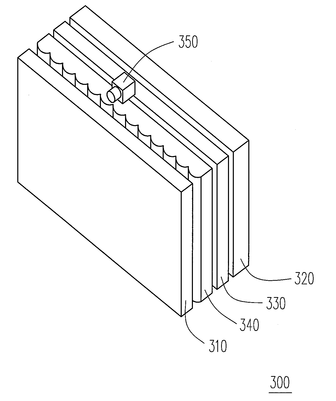
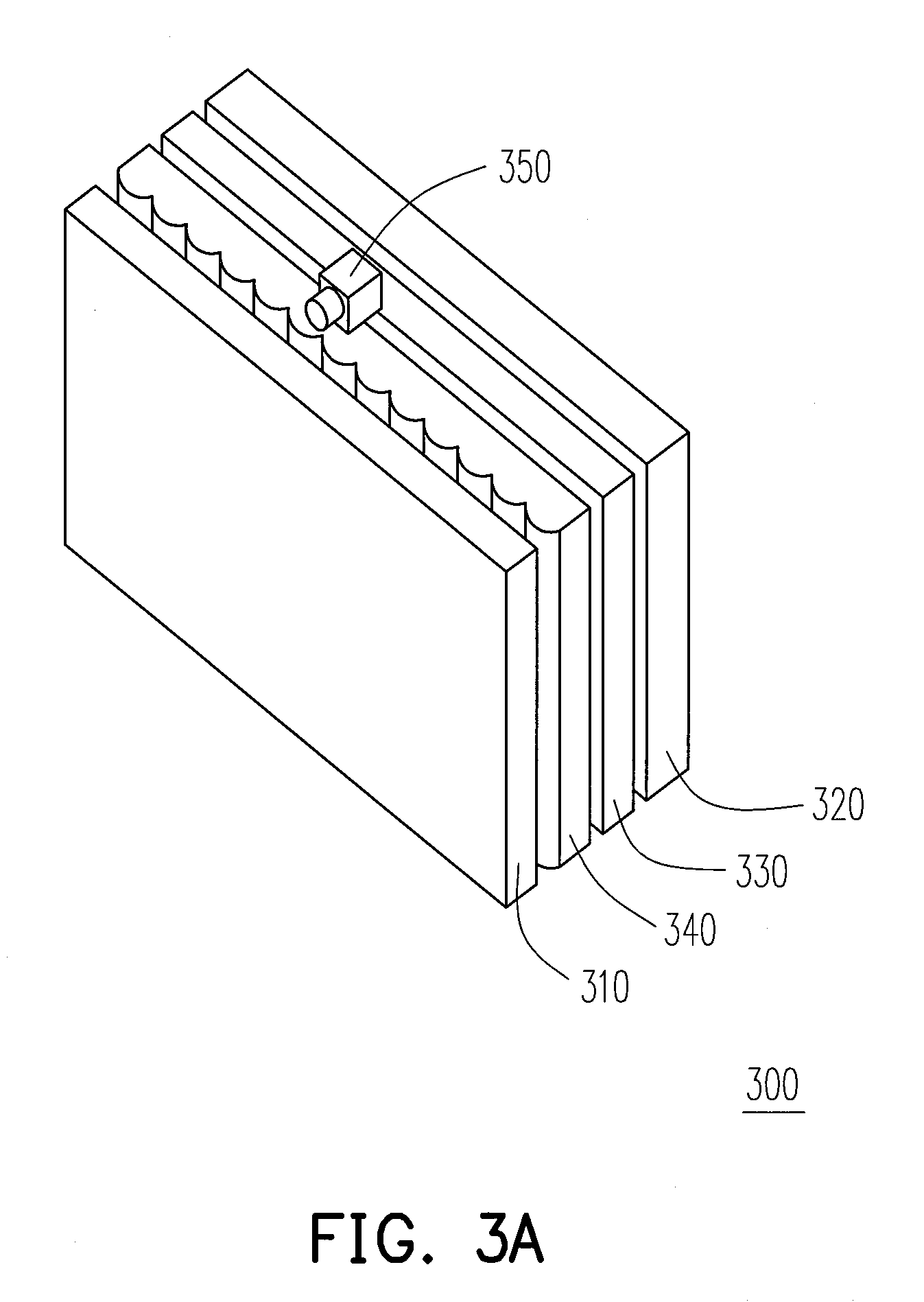
[0049]FIG. 4A is a schematic view illustrating a stereoscopic display apparatus according to the present invention. FIG. 4B is a block diagram illustrating the stereoscopic display apparatus of FIG. 4A. Referring to FIG. 4A and FIG. 4B, the stereoscopic display apparatus 400 is similar with the stereoscopic display apparatus 300 shown in FIG. 3A, wherein the same or similar numerals represent the same or similar elements, respectively. Additionally, function of the stereoscopic display apparatus 400 is also similar with that of the stereoscopic display apparatus 300. In other words, the stereoscopic display apparatus 400 can track viewer's position or can be watched by multiple viewers.

[0050]The backlight module of stereoscopic display apparatus 400 is a dynamic backlight module 420 having a plurality of light-emitting regions R1˜R4. It is noted that control unit and optical lens array are omitted in FIG. 4A. In the stereoscopic display apparatus 400, the graphic card 370 outputs an...

second embodiment

[0059]FIG. 5A is a schematic view illustrating a stereoscopic display apparatus according to the present invention. FIG. 5B is a block diagram illustrating the stereoscopic display apparatus of FIG. 5A. Referring to FIG. 5A, the stereoscopic display apparatus 500 is modified from the stereoscopic display apparatus 300, wherein the same or similar numerals represent the same or similar elements, respectively. It is noted that control unit and optical lens array are omitted in FIG. 5A. The tracking panel 530 of the stereoscopic display apparatus 500 is different from the above-mentioned tracking panel 330. In addition to the plurality of slit sets 532 and 534, the slit set 532 includes a plurality of transmissive areas 532A arranged in array and the slit set 534 includes a plurality of transmissive areas 534A arranged in array. In the present embodiment, only two slit sets 532 and 534 are described for illustration, the tracking panel 530 may have more than two slit sets.

[0060]Referri...


PUM


Abstract

A stereoscopic display apparatus and a display method are provided. The stereoscopic display apparatus includes a display panel, a dynamic-backlight module, a tracking panel, an optical lens array. The display has an updated region and a non-updated region during a frame period the display panel displays according a first synchro-signal. The dynamic-backlight module has a plurality of light-emitting regions and the light-emitting regions are turned-on according to a second synchro-signal. The first synchro-signal and the second synchro-signal are synchronal. During the frame period, parts of the light-emitting regions corresponding to the updated region are synchronally turned-on and parts of the light-emitting regions corresponding to the non-updated region are synchronally turned-off. A light provided by at least the part of the light-emitting regions turned-on passes through one silt set and the display panel such that one of the single-eye images is only displayed by the non-updated region.

Description

CROSS-REFERENCE TO RELATED APPLICATION[0001]This application claims the priority benefit of Taiwan application serial no. 97151118, filed on Dec. 26, 2008. The entirety of the above-mentioned patent application is hereby incorporated by reference herein and made a part of this specification.BACKGROUND OF THE INVENTION[0002]1. Field of the Invention[0003]The present invention relates to a stereoscopic display apparatus and a display method.[0004]2. Description of Related Art[0005]As technology advances and develops, people's eagerness for better material life and spiritual life are increasing without a pause. When it comes to the spiritual life, in the world of technology, most people have the desire to realize their imagination and to experience it vividly with the help of various display devices. For this reason, how to develop display devices suitable for displaying three-dimensional images has become the goal to the manufacturers in the field.[0006]In view of the appearance, the ...

Claims


Application Information

Patent Timeline
IPC IPC(8): H04N13/04
CPCG09G3/003G09G3/342G09G2300/023H04N13/398H04N13/32H04N13/376G09G2354/00
Inventor LIOU, JIAN-CHIUNLEE, KUENHUANG, JUI-FENG
Owner IND TECH RES INST
Learn More