Cable receiving unit

a technology of receiving unit and cable, applied in the direction of electrical equipment, electric digital data processing, instruments, etc., to achieve the effect of avoiding multiple readings

Active Publication Date: 2010-07-01
LAPP ENG
View PDF61 Cites 15 Cited by
  • Summary
  • Abstract
  • Description
  • Claims
  • Application Information

AI Technical Summary

Benefits of technology

[0102]In particular, this also has the effect, when the information carrier units are addressed by the read / write device, of avoiding multiple reading-out by multiple information carrier units, and consequently misinterpretation of the data read out.
[0103]It is still better if the distances correspond to at least 2.5 times the effective antenna range of the information carrier units in the direction of the nearest information carrier unit.

Problems solved by technology

In the case of cable receiving units of this kind, there is often the problem of reliably transmitting to a user data concerning said units or an installation environment or specifications of said environment.

Method used


Image

  • Cable receiving unit
  • Cable receiving unit
  • Cable receiving unit

Examples


Embodiment Construction

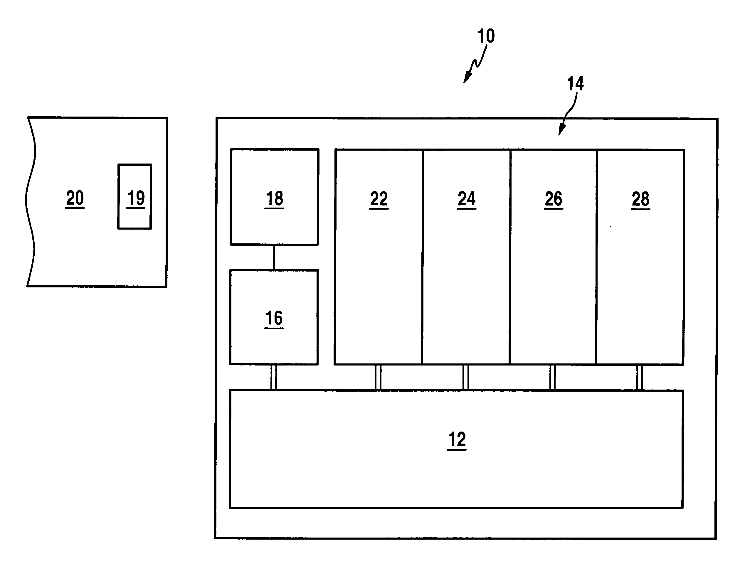
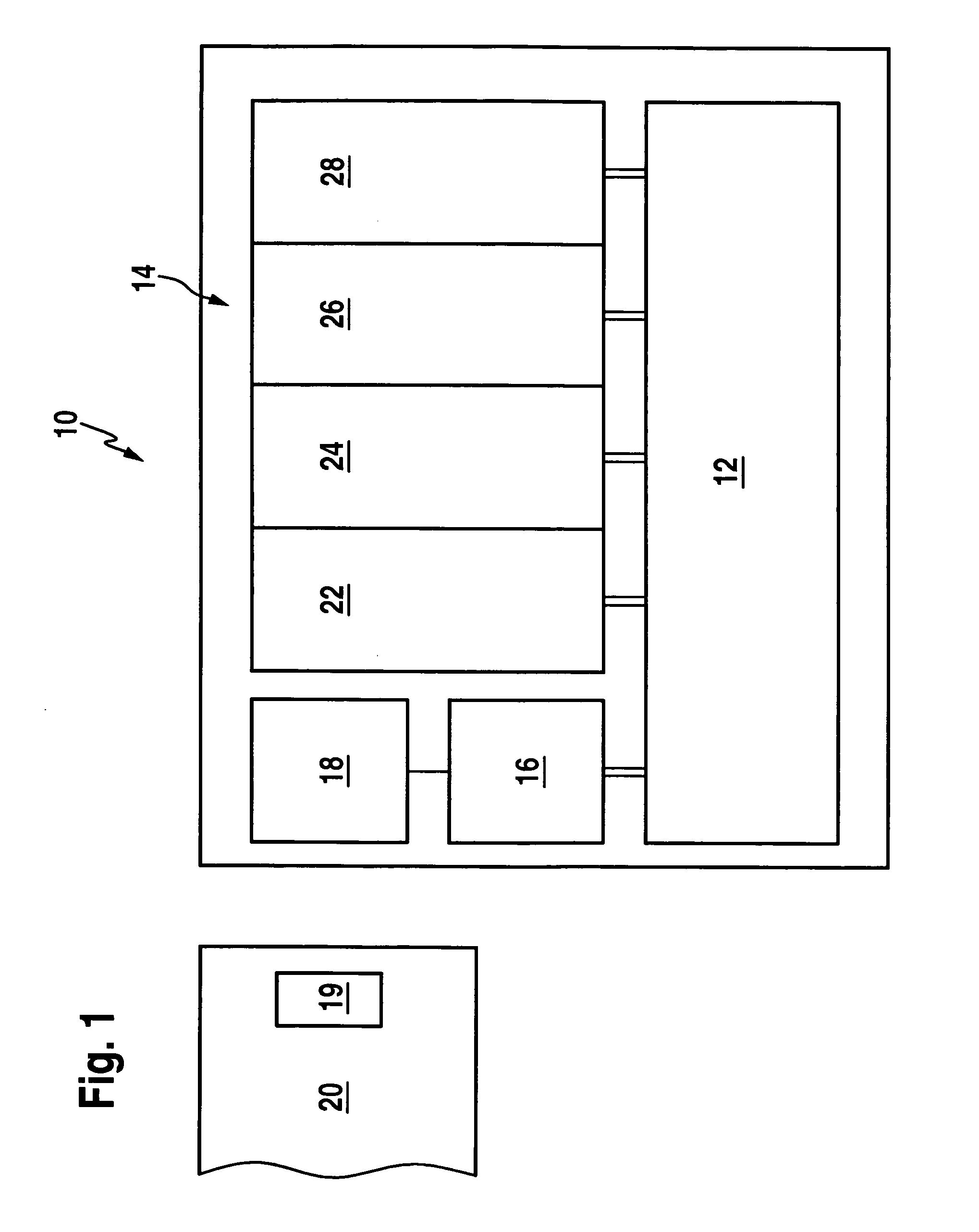
[0226]A first exemplary embodiment of an information carrier unit 10 to be used according to the invention, represented in FIG. 1, comprises a processor 12, to which a memory designated as a whole by 14 is linked, the memory preferably being formed as an EEPROM.

[0227]Also connected to the processor 12 is an analog part 16, which interacts with an antenna unit 18.

[0228]When there is electromagnetic coupling of the antenna unit 18 to an antenna unit 19 of a stationary or mobile read / write device designated as a whole by 20, the analog part 16 is then capable on the one hand of generating, with the required power, the electrical operating voltage that is necessary for the operation of the processor 12 and the memory 14, as well as the analog part 16 itself, and on the other hand of making available to the processor 12 the information signals transmitted by electromagnetic field coupling at a carrier frequency or transmitting information signals generated by the processor 12 by way of t...


PUM


Abstract

In order to reliably and simply acquire data for a cable receiving unit for a cable portion, the cable receiving unit is associated with an information carrier unit from which information can be read out by electromagnetic field coupling.

Description

[0001]This application is a continuation of International application No. PCT / EP2008 / 059196 filed on Jul. 14, 2008.[0002]This patent application claims the benefit of International application No. PCT / EP2008 / 059196 of Jul. 14, 2008 and German applications No. 10 2007 035 047.5 of Jul. 19, 2007 and No. 10 2007 036 948.6 of Aug. 4, 2007, the teachings and disclosure of which are hereby incorporated in their entirety by reference thereto.BACKGROUND OF THE INVENTION[0003]The invention relates to a cable receiving unit for a cable portion.[0004]Cable receiving units of this kind are usually plug-in connector elements, cable glands or the like, elements connected to a cable portion which, with pre-prepared cable portions, are sold as a ready-assembled cable assembly, or cable receiving units which are usually fitted in items of equipment and serve the purpose of establishing a connection between the equipment and a cable portion.[0005]In the case of cable receiving units of this kind, the...

Claims


Application Information

Patent Timeline
Patent Type & Authority Applications(United States)
IPC IPC(8): H05K7/00
CPCH02G3/0616H02G3/0462
Inventor LAPP, SIEGBERT
Owner LAPP ENG
Why Eureka
Try Eureka