Reinforced Doctor Blade Assembly Seal and Printer Cartridge Employing the Reinforced Seal

a technology of reinforced seals and doctor blades, applied in the field of image forming devices, can solve the problems of large shock force, potential drop, and more leakage paths

Active Publication Date: 2010-07-01
LEXMARK INT INC
View PDF7 Cites 53 Cited by
  • Summary
  • Abstract
  • Description
  • Claims
  • Application Information

AI Technical Summary

Benefits of technology

[0014]In another aspect of the present invention, a printer cartridge includes a housing having a reservoir for holding toner, a developer roll supported by the housing and operable to receive toner from the reservoir and transfer the toner to a photoconductive drum, a doctor blade assembly supported by the housing adjacent to the developer roll and having a doctor blade and a bracket for positioning the doctor blade to form a nip with the developer roll to control the amount of toner metered onto the developer roll, the bracket also disposed adjacent a portion of the housing such that a gap is defined between the bracket and the housing portion, and the above-described reinforced seal disposed through the gap to provide sealing of the gap between the bracket and the housing portion to prevent potential leakage of toner in a predetermined direction of flow through the gap and from the printer cartridge. The adhesive coating on the non-laminated portion of the base strip adapts the reinforced seal at the non-laminated portion for attachment to the housing at least downstream of the gap.

Problems solved by technology

The printer cartridge 10 has the potential to be dropped and thus exposed to large shock forces during shipping separate from the printer.
This blow out and dislocation of the seal 12 causes two problems.
Also, the foam causes more leak paths to propagate than the boPET polyester seal, requiring the application of wax to fill the anticipated leak paths.

Method used


Image

  • Reinforced Doctor Blade Assembly Seal and Printer Cartridge Employing the Reinforced Seal
  • Reinforced Doctor Blade Assembly Seal and Printer Cartridge Employing the Reinforced Seal
  • Reinforced Doctor Blade Assembly Seal and Printer Cartridge Employing the Reinforced Seal

Examples


Embodiment Construction

[0023]The present invention now will be described more fully hereinafter with reference to the accompanying drawings, in which some, but not all embodiments of the invention are shown. Indeed, the invention may be embodied in many different forms and should not be construed as limited to the embodiments set forth herein; rather, these embodiments are provided so that this disclosure will satisfy applicable legal requirements. Like numerals refer to like elements throughout the views.

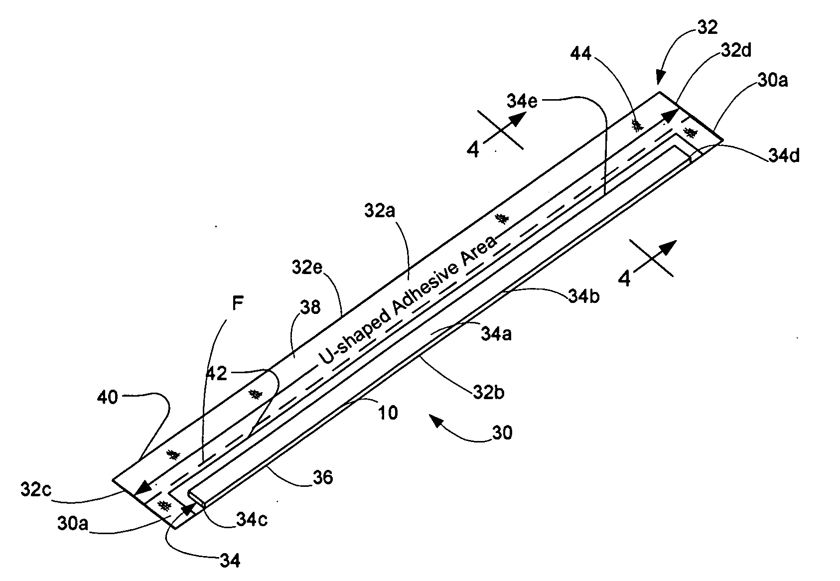
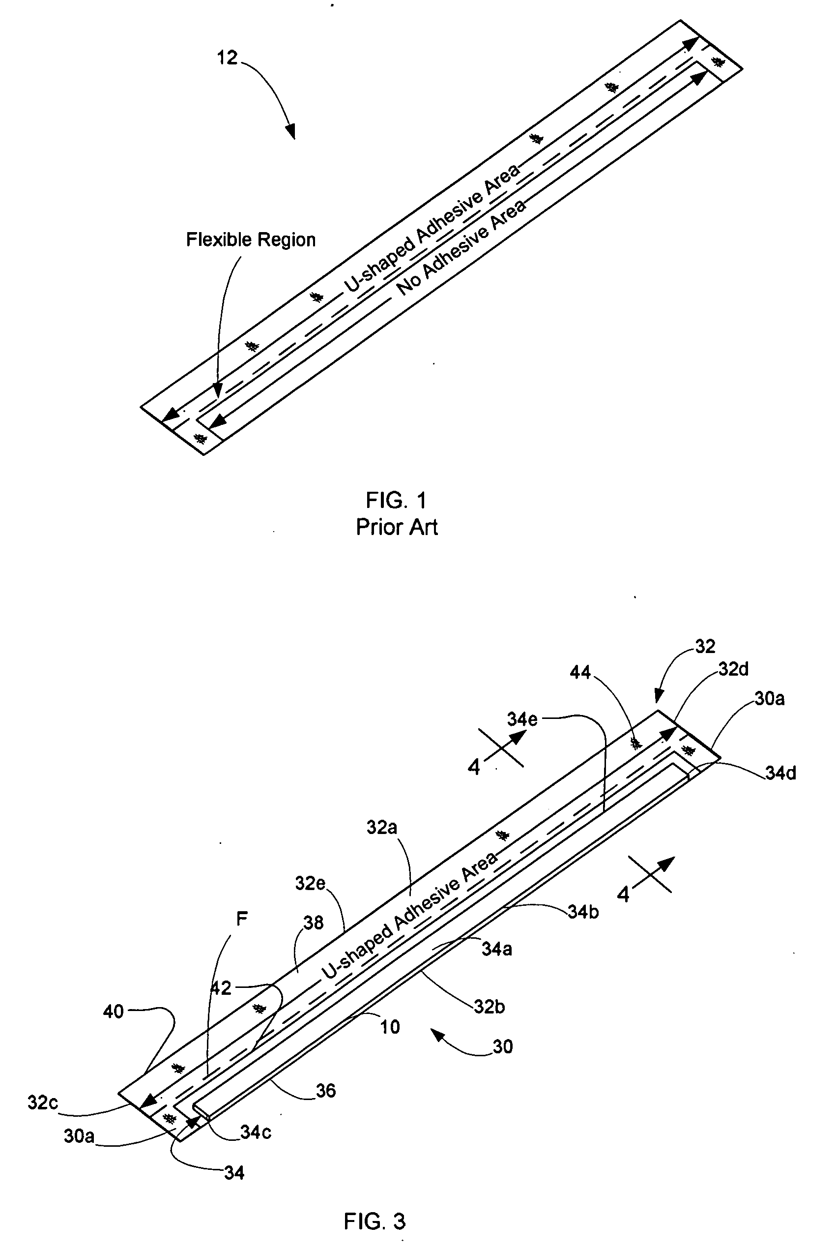
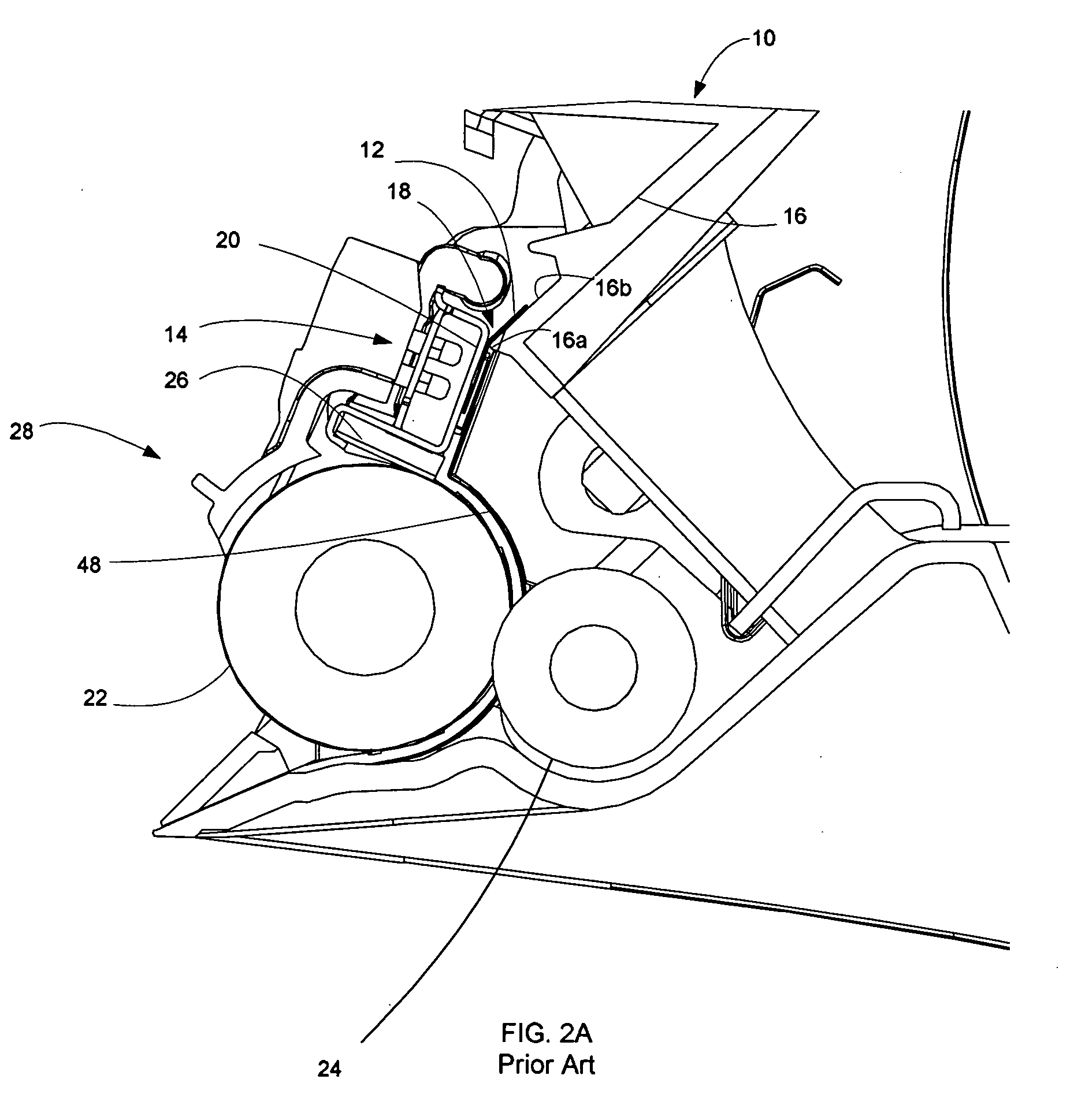
[0024]Referring now to FIGS. 3-5, there is illustrated an exemplary embodiment of a reinforced seal of the present invention, generally designated 30, for sealably closing the gap 18 between the doctor blade assembly 14 and the housing 16 of the printer cartridge 10. The reinforced seal 30 basically has partially a single layered construction and partially a two layered, laminated construction, comprised of an elongated base strip 32 of a flexible plastic film and an elongated supplemental strip 34 of a ...


PUM


Abstract

A reinforced doctor blade assembly seal includes a base strip of a flexible plastic film having a thickness, a surface of predetermined area bounded by multiple edges, and a foldable region extending length-wise between one pair of the multiple edges and spaced from and located intermediately between another pair of the multiple edges. The seal also includes a supplemental strip of a flexible plastic film having a thickness and a surface of predetermined area bounded by multiple edges. The supplemental strip is laminated on the base strip offset from and along one side of the foldable region on the base strip such that the base strip has adjacent laminated and non-laminated portions along opposite sides of the foldable region with the laminated portion having a greater thickness than the non-laminated portion. The seal has an attaching mechanism in the form of an adhesive coating on the non-laminated portion of the base strip. The seal is employed in a printer cartridge.

Description

CROSS REFERENCES TO RELATED APPLICATIONS[0001]None.BACKGROUND[0002]1. Field of the Invention[0003]The present invention relates generally to an image forming device and, more particularly, to a reinforced doctor blade assembly seal and a printer cartridge employing the reinforced seal.[0004]2. Description of the Related Art[0005]An image forming device, such as a laser printer and the like, includes a drum having a photoconductive outer cylindrical surface charged to a uniform electrical potential and then selectively exposed to light in a pattern corresponding to an original image. Those areas of the photoconductive surface exposed to light are discharged thus forming a latent electrostatic image thereon. A developer material, such as toner, having an electrical charge such that the toner is attracted to the discharged area of the photoconductive surface operates in contact with the photoconductive surface. The drum developed image then rotates toward a transfer station. A recordin...

Claims


Application Information

Patent Timeline
Patent Type & Authority Applications(United States)
IPC IPC(8): G03G15/08
CPCG03G15/0812G03G21/1832
Inventor LEEMHUIS, JAMES RICHARDNEWMAN, BENJAMIN KEITH
Owner LEXMARK INT INC
Why Eureka
Try Eureka