
Inlet Guide Vanes and Gas Turbine Engine Systems Involving Such Vanes

Active Publication Date: 2010-07-01
RAYTHEON TECH CORP
View PDF20 Cites 22 Cited by
  • Summary
  • Abstract
  • Description
  • Claims
  • Application Information

AI Technical Summary

Benefits of technology

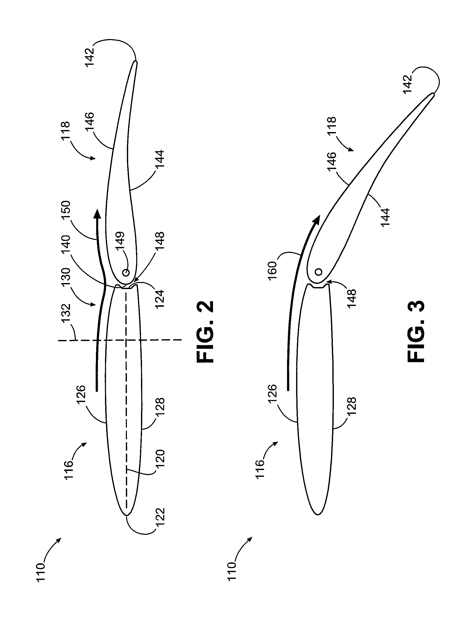
[0006]An exemplary embodiment of an inlet guide vane assembly for a gas turbine engine comprises: multiple inlet guide vanes; a first of the inlet guide vanes having a fixed strut and a variable flap; the variable flap being located downstream of the fixed strut and being movable with respect thereto; the fixed strut exhibiting chordwise asymmetry operative to reduce a tendency of gas flowing along surfaces of the inlet guide vane to separate therefrom.

Problems solved by technology

Unfortunately, some positions of the flap may result in unwanted airflow separation from the surface of the flap, resulting in a turbulent airflow.
Such airflow tends to increases wear on the components downstream of the inlet guide vane.

Method used


Image

  • Inlet Guide Vanes and Gas Turbine Engine Systems Involving Such Vanes
  • Inlet Guide Vanes and Gas Turbine Engine Systems Involving Such Vanes
  • Inlet Guide Vanes and Gas Turbine Engine Systems Involving Such Vanes

Examples


Embodiment Construction

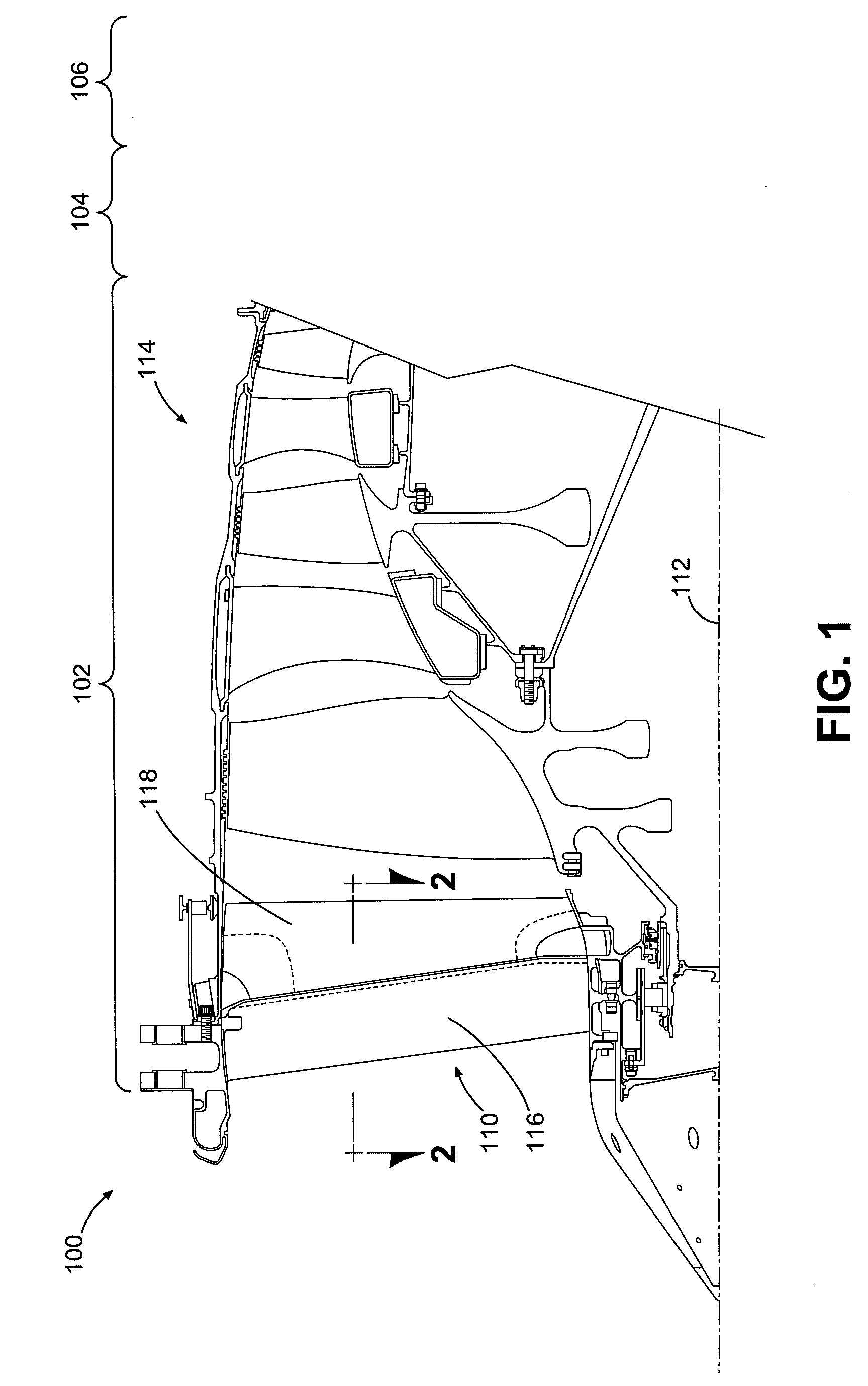
[0013]Inlet guide vanes and gas turbine engine systems involving such vanes are provided, several exemplary embodiments of which will be described in detail. In this regard, some embodiments involve the use of a fixed strut that exhibits chordwise asymmetry (i.e., the fixed strut is asymmetric with respect to the chord line, which extends from the leading edge to the trailing edge of the strut). Such asymmetry may reduce a tendency of gas flowing along surfaces of the inlet guide vane to separate, thus maintaining laminar flow along the surfaces. In some embodiments, the chordwise asymmetry is expressed by an aft portion of the fixed strut (which is located adjacent to the suction side surface of a downstream flap) that enables turning of gas prior to the gas reaching the flap (e.g., turning with respect to the axial flow direction). As such, some of the turning of the gas is accomplished by the strut, thereby potentially resulting in more overall turning of the gas. Regardless of t...


PUM


Abstract

Inlet guide vanes and gas turbine engine systems involving such vanes are provided. In this regard, a representative an inlet guide vane for a gas turbine engine includes: a fixed strut; and a variable flap located downstream of the fixed strut and being movable with respect thereto; the fixed strut having a leading edge, a trailing edge and side surfaces extending between the leading edge and the trailing edge, the side surfaces being asymmetric with respect to each other.

Description

BACKGROUND[0001]1. Technical Field[0002]The disclosure generally relates to gas turbine engines.[0003]2. Description of the Related Art[0004]Some gas turbine engines include variable geometry inlet guide vanes that are positioned upstream of the compressors (also known as “fans” in some implementations) of the engines. Such an inlet guide typically includes a fixed strut and a movable flap positioned adjacent to and downstream of the fixed strut. The flap can be selectively positioned to alter deflection of airflow to downstream components of the engine. Unfortunately, some positions of the flap may result in unwanted airflow separation from the surface of the flap, resulting in a turbulent airflow. Such airflow tends to increases wear on the components downstream of the inlet guide vane.SUMMARY[0005]Inlet guide vanes and gas turbine engine systems involving such vanes are provided. In this regard, an exemplary embodiment of an inlet guide vane for a gas turbine engine comprises: a ...

Claims


Application Information

Patent Timeline
IPC IPC(8): F02C9/22F01D17/16
CPCF01D5/146F01D17/162F02C9/22F05B2240/31F04D29/563
Inventor CARROLL, CHRISTIAN A.
Owner RAYTHEON TECH CORP
Learn More