Magnet Embedded Rotor, Electric Motor Using the Same Rotor, and Compressor Using the Same Motor

a technology of embedded rotors and electric motors, which is applied in the direction of magnetic circuit rotating parts, magnetic circuit shapes/forms/construction, piston pumps, etc., can solve the problems of iron loss occurring at the rotation of electric motors, reducing efficiency, and flux increasing calking torque, so as to increase the output torque of electric motors, reduce calking torque, and reduce the variation in magnetic flux density

Active Publication Date: 2010-07-01
FUJITSU GENERAL LTD
View PDF3 Cites 27 Cited by
  • Summary
  • Abstract
  • Description
  • Claims
  • Application Information

AI Technical Summary

Benefits of technology

[0024]In the invention as defined in claim 1, the magnet embedded rotor in which the permanent magnets are embedded in the iron core of the rotor at a fixed interval comprises the notch part and the first protruding part formed on the outer face between the salient poles in said iron core of the rotor corresponding to said multiple permanent magnets, the non-magnetic part for preventing the short circuit of magnetic flux formed at the bilateral edges of said permanent magnets, the bridge part between the non-magnetic part and the notch part which is narrowed to an extent to cause a magnetic saturation, and the second protruding part extending to the direction of the outer face formed at said notch part. Consequently, it is possible to increase the output torque of the electric motor and reduce the calking torque and moreover, vibration and noise (torque ripple). Thus, the output waves closer to sine waves can be produced.
[0025]In the invention as defined in claim 2, the notch part formed in such a manner that it changes gradually over a range from the outer face of the salient pole to the first protruding part enables to decrease the variation in the magnetic flux density and then components of higher harmonics appearing on induced voltage waves as much as possible.
[0026]In the invention as defined in claim 3, since the central angle between the inflection points at which the bilateral notch part on the outer face of the salient pole is started is set at 40˜48°, the top of the wave can become closer to sine wave.
[0027]In the invention as defined in claim 4, the multiple second protruding parts are formed with different heights at a fixed interval and the distances with the stator and with void part are made different. Consequently, the waves at both the sides expand so more than the tops of the waves that the waves can be closer to sine waves.
[0028]In the invention as defined in claim 5, the permanent magnets are formed in a V-letter shape expanding to the outer direction, which enables to reduce the torque ripple as the output is increased.
[0029]In the invention as defined in claim 6, the electric motor installs the stator and the rotor and utilizes the magnet embedded rotor wherein the permanent magnets are embedded in the iron core of said rotor in a fixed interval. Said stator is a concentrated winding stator wherein each stator winding winds intensively at the multiple stator cogs extending from the stator yoke to the center at a fixed interval. Said rotor comprises the notch parts at the first protruding part and both sides of the first protruding part on the outer face between the salient poles corresponding to said multiple magnets, the non-magnetic part for preventing the short circuit of the magnetic flux at both the edges of said permanent magnets, and the second protruding part at said notch part which extends to the direction of the outer face and wherein the bridge part between the non-magnetic part and said notch part is narrowed to an extent to cause a magnetic saturation. Consequently, when the electric motor is used for consumer products and industrial equipments, the output torque of the motor can be increased and moreover, the calking torque and vibration / noise (torque ripple) can be decreased.

Problems solved by technology

Components of higher harmonics are contained with a large quantity, so that the iron loss occurring at the rotation of the electric motor becomes so large that the efficiency decreases.
However, a leaked magnetic flux occurs at the adjacent salient pole 20 though the facing stator 10 from the non-magnetic part 17 and this leaked magnetic flux increases the calking torque and consequently increases noise, which was a problem.
Thus, it was difficult to realize an induced voltage with a high peak level and less components of higher harmonics.

Method used


Image

  • Magnet Embedded Rotor, Electric Motor Using the Same Rotor, and Compressor Using the Same Motor
  • Magnet Embedded Rotor, Electric Motor Using the Same Rotor, and Compressor Using the Same Motor
  • Magnet Embedded Rotor, Electric Motor Using the Same Rotor, and Compressor Using the Same Motor

Examples


embodiment 1

[0050]Embodiments of the present invention are described below, based on the drawings.

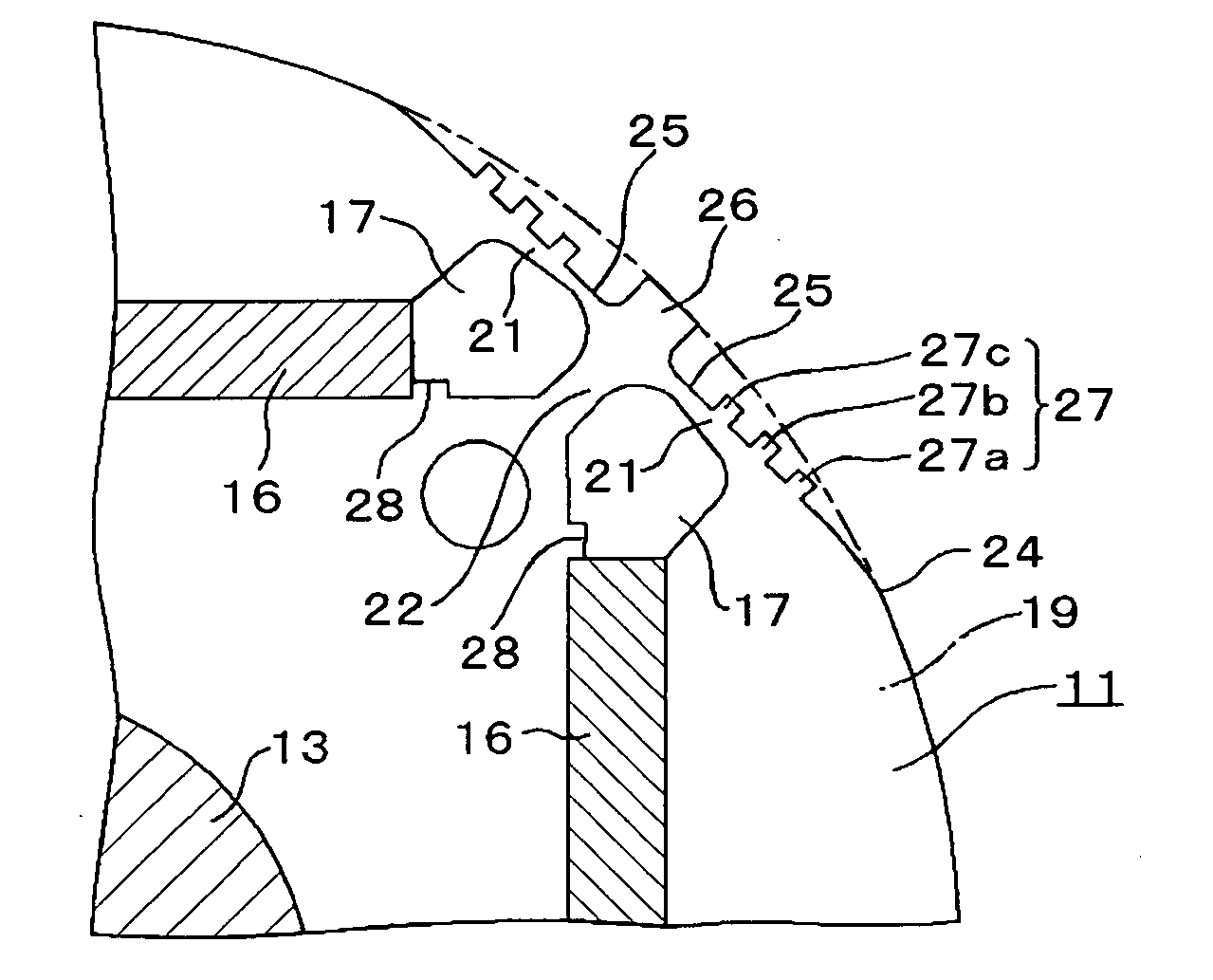
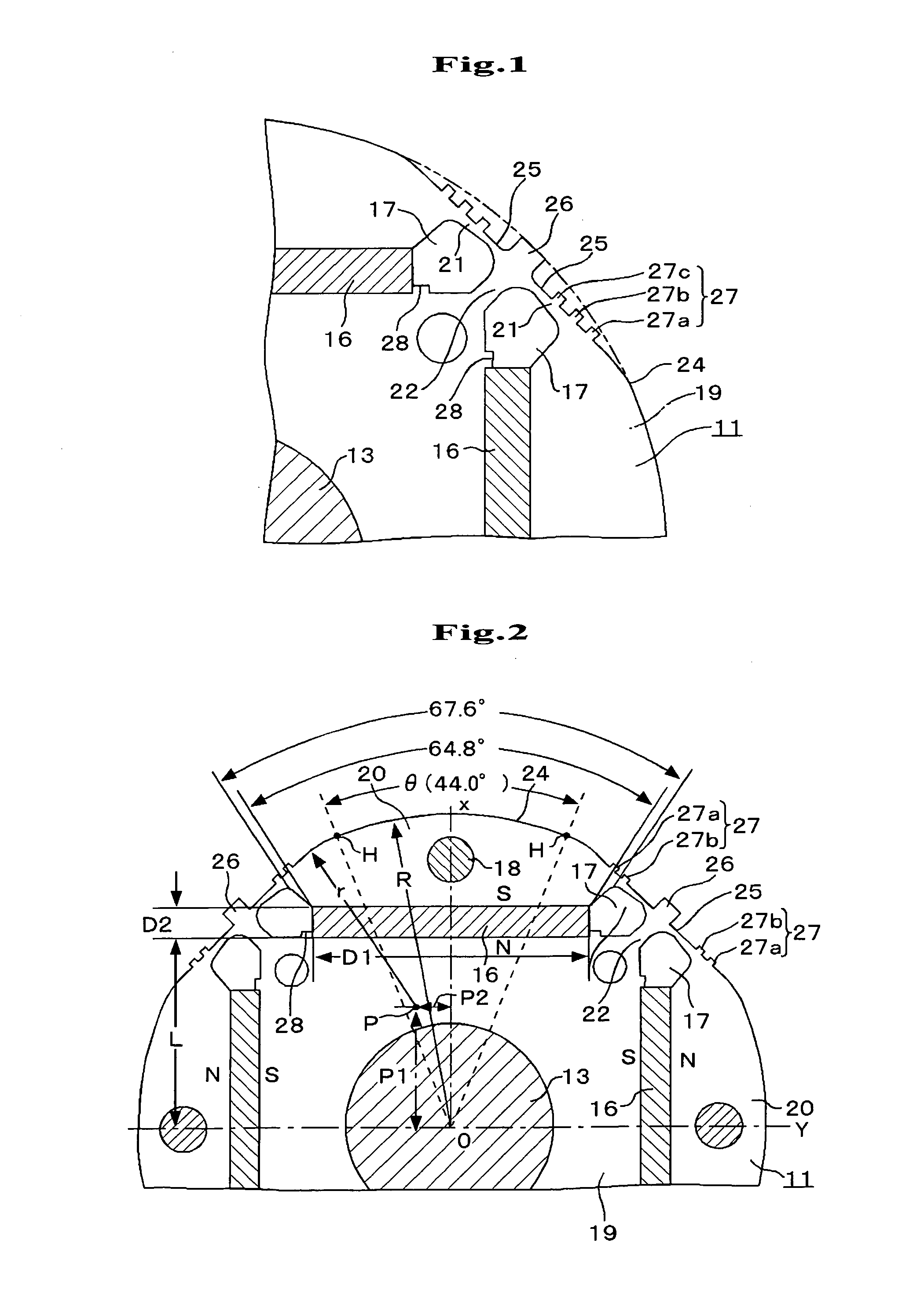
[0051]In FIGS. 1 and 2, a rotor 11 comprises the iron core of the rotor in which multiple silicon steel plates are laminated, four permanent magnets 16, a rotation axis 13 at the center and rivets for fixation 18 at four sites near the outer face.

[0052]In iron core 19 of said rotor, said permanent magnets 16 are the long hand D1 (e.g. 26.5 mm)×the short hand D2 (e.g. 2.8 mm) in size with the radius R (e.g. 30.00 mm) and embedded at a distance L (e.g. 18.02 mm) in parallel to the axes X and Y passing through the central point 0. The salient poles comprise outer faces 24 corresponding to the long hands of the permanent magnets. At both the edges of these permanent magnets 16, non-magnetic parts 17 including the void for preventing the short circuit of the magnetic flux are formed and reinforced rib parts 22 are between the adjacent two non-magnetic parts 17. The first protruding part 26 is formed at ...

embodiment 2

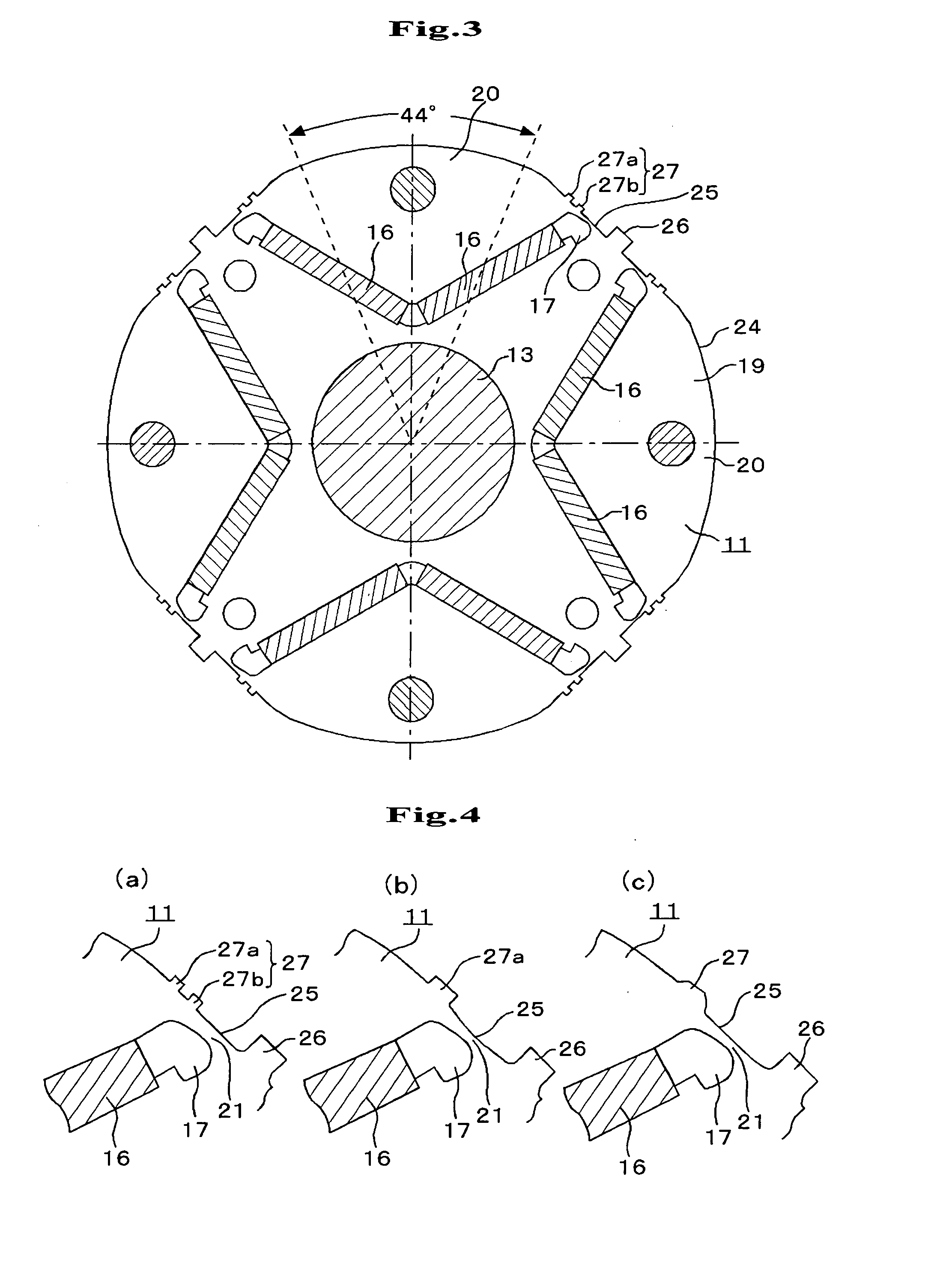
[0064]FIG. 3 shows Embodiment 2 of the present invention in which permanent magnets 16 are arranged in a V-letter shape. When the permanent magnets 16 are arranged in a V-letter shape, the output improves, but the effect to reduce the calking torque and vibration / noise (torque ripple) which are the objects of the present invention, is hardly different from that in Embodiment 1. The other configurations are not different from those in FIG. 2.

[0065]FIG. 4 (a) shows an enlarged view of FIG. 3 with two second protruding parts 27a and 27b. FIG. 4 (b) shows an embodiment in which the one second protruding part 27a rises up sharply at both the sides and FIG. 4 (c) shows an embodiment in which the one second protruding part 27a rises up smoothly at both the sides.

[0066]The experimental action and effect of the rotor 11 (FIGS. 3 and 4) in Embodiment 2 are described in FIG. 11.

[0067]As for calking torque, the embodiment with the one second protruding part 27 which is smooth as shown in FIG. 4...


PUM


Abstract

A magnet embedded rotor is provided in which permanent magnets are embedded in the iron core of the rotor at a fixed interval. Notch parts are formed at the first protruding part and both the sides of the first protruding parts on the outer face between salient poles in the iron core of the rotor correspond to the multiple permanent magnets. Non-magnetic parts for preventing the short circuit of magnetic flux are formed at both the edges of the permanent magnets. A bridge part between the non-magnetic parts and the notch parts are narrowed as much as possible to an extent to cause a magnetic saturation, and one or multiple of the second protruding part extending to the direction of the outer face are formed at the notch parts.

Description

FIELD OF THE INVENTION[0001]The present invention relates to a magnet embedded rotor in which permanent magnets are embedded in the iron core of the rotor and an electric motor using the rotor in electric motors and generators used for consumer products, industrial equipments and others.BACKGROUND OF THE INVENTION[0002]As shown in FIG. 12, a known electric motor using this type of magnet embedded rotor has a rotor 11 and a void part 12 inside a stator 10. The rotor 11 comprises four permanent magnets 16 embedded in the form of a square approximately in the iron core 19 of the rotor in which multiple silicon steel plates are laminated and fixed with rivets 18, a rotation axis 13 mounted at the center, and non-magnetic parts 17 at the bilateral edges of each permanent magnet 16 including voids for preventing flux short circuit and others. The parts of the iron core of the rotor facing the outer side of each permanent magnet 16 comprise salient poles 20.[0003]The stator 10 comprises si...

Claims


Application Information

Patent Timeline
Patent Type & Authority Applications(United States)
IPC IPC(8): F04B35/04H02K1/27
CPCH02K1/276H02K29/03H02K1/2766
Inventor FUKUDA, YOSHICHIKAPATISONTICHAROEN, PAIROJKIKUCHI, YUUSUKENAKAGAWARA, HIROKI
Owner FUJITSU GENERAL LTD
Why Eureka
Try Eureka