Exercise Pedal

Inactive Publication Date: 2010-07-01
KO MING JEN
View PDF7 Cites 21 Cited by
  • Summary
  • Abstract
  • Description
  • Claims
  • Application Information

AI Technical Summary

Benefits of technology

[0006]The primary object of the present invention is to provide an exercise pedal that the plate member and the two seats are capable of being used solely or together to vary different exercise motions.
[0007]Another object of the present invention is to provide an exercise pedal that the seats are placed in the first recesses of the plate member to lower storing size and be portable easily.

Problems solved by technology

However, such a conventional exercise pedal is only used to be stepped upward and downward by the user as walking on the stairs, having single function.

Method used


Image

  • Exercise Pedal
  • Exercise Pedal
  • Exercise Pedal

Examples


Embodiment Construction

[0037]The present invention will be clearer from the following description when viewed together with the accompanying drawings, which show, for purpose of illustrations only, the preferred embodiment in accordance with the present invention.

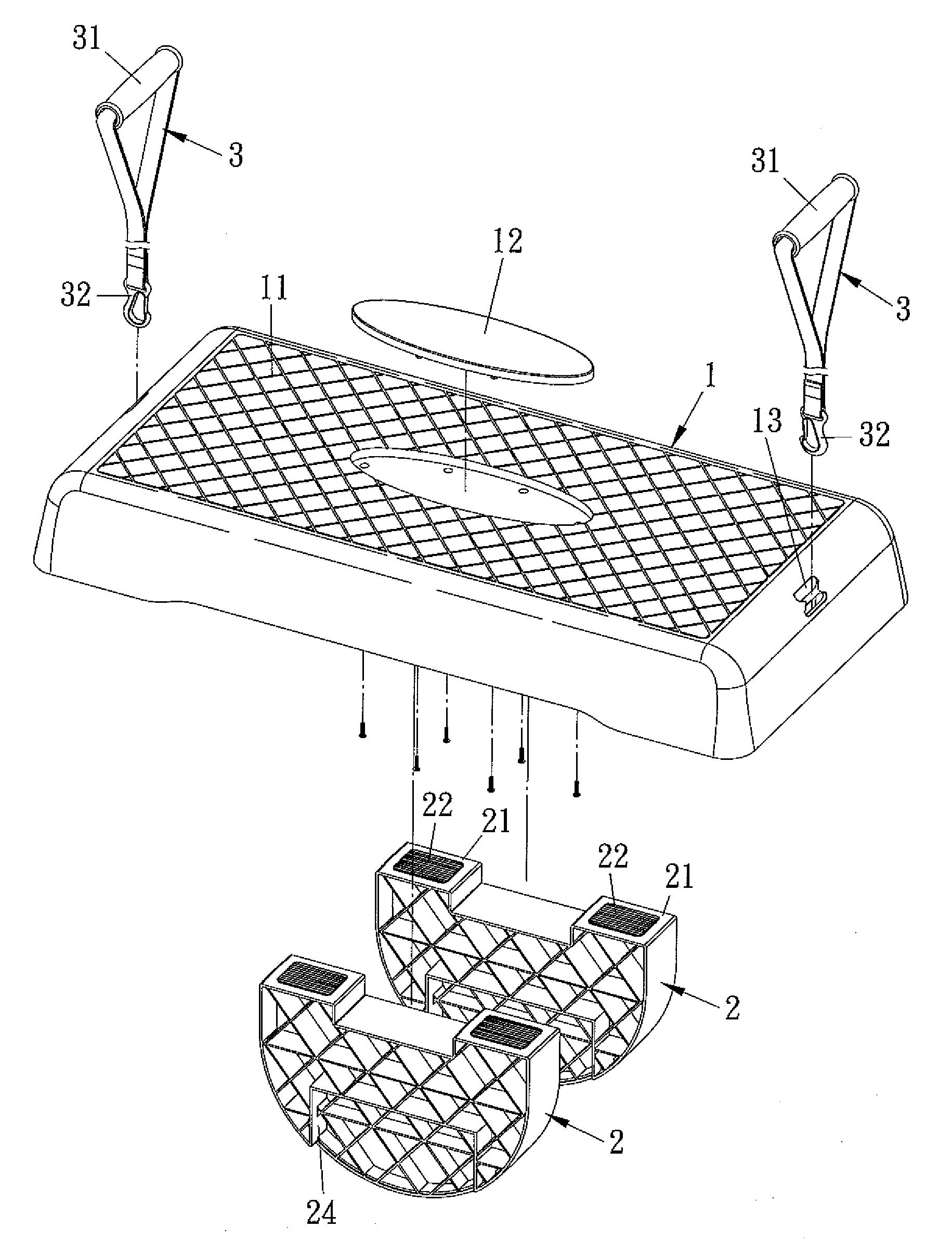
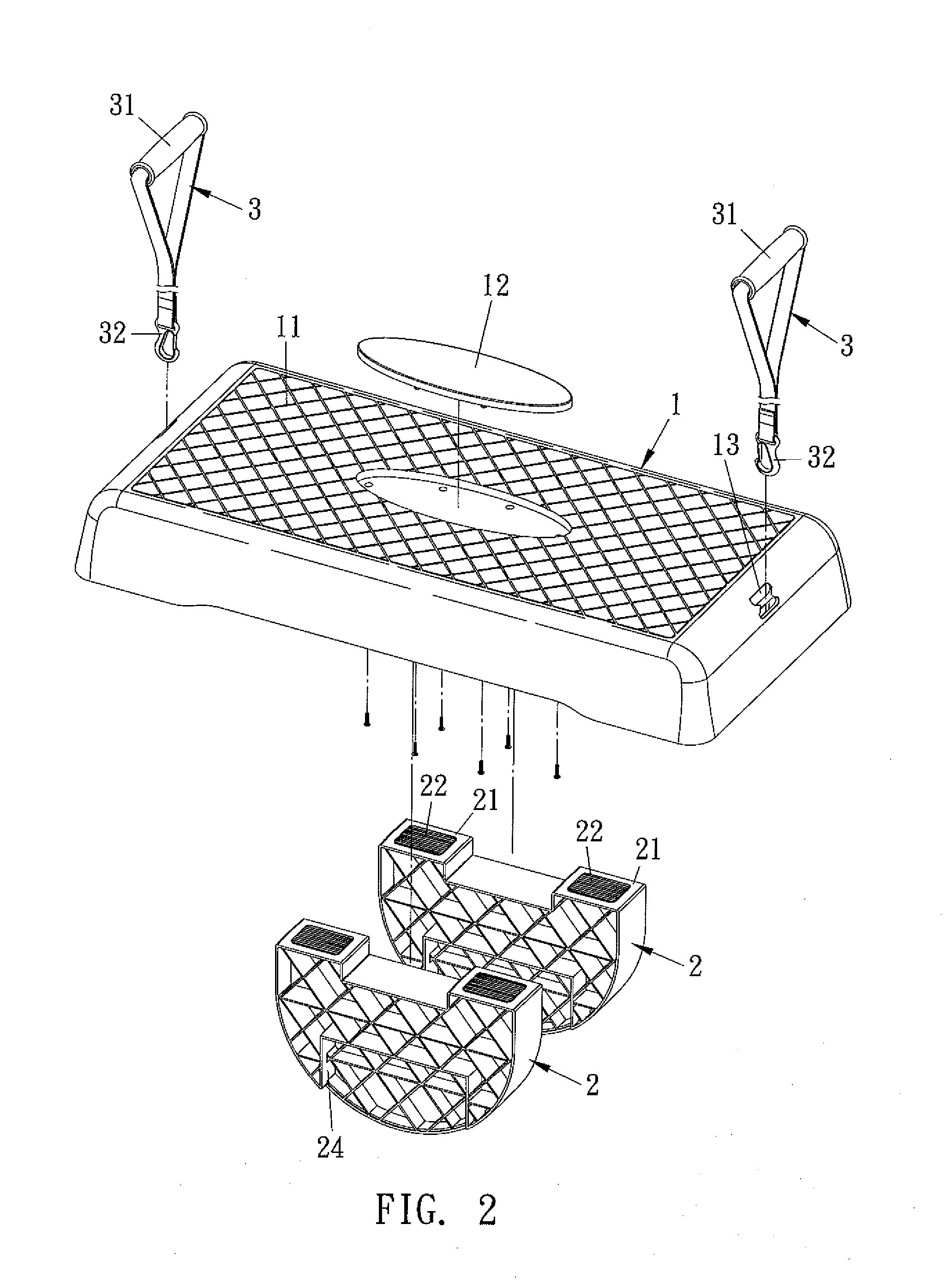
[0038]Referring to FIGS. 2-9, an exercise pedal in accordance with a preferred embodiment of the present invention comprises a plate member 1, two seats 2, and two flexible ropes 3, wherein the plate member 1 includes anti-slip patterns 11 formed on a top surface thereof, a decorative member 12 disposed at a central portion of the top surface thereof, two holes 13 mounted on two sides thereof respectively, and a receiving cavity 14 fixed on a bottom surface thereof. The cavity 14 includes a first partition 141 fixed on a central portion thereof, two second partitions 142 arranged proximate to two ends thereof, and between the first partition 141 and the second partitions 142 are defined first recesses 143, between the second partitions 142 and tw...


PUM


Abstract

An exercise pedal comprising: a plate member including a receiving cavity fixed on a bottom surface thereof, and the receiving cavity including a plurality of partitions to space a number of recesses; a seat formed in a semicircle shape to be vertically, upside down or horizontally retained to the recesses based on demands, such that the plate member and the two seats are capable of being used solely or together to vary different exercise motions. Furthermore, the seats are placed in the first recesses of the plate member to lower storing size and be portable easily.

Description

BACKGROUND OF THE INVENTION[0001]1. Field of the Invention[0002]The present invention relates to an exercise pedal that is capable of varying different exercise motions.[0003]2. Description of the Prior Art[0004]As shown in FIG. 1, a conventional exercise pedal comprises a rectangular body 10 including anti-slip patterns formed on a top surface thereof, two inserting slots arranged on two sides of a bottom surface thereof to be placed on the ground, such that the top surface of the exercise pedal serves to be stepped by a user, or the body 10 includes two adjustable foots 20 disposed in the inserting slots of the body 10 to be placed on the ground so as to adjust a height of the exercise pedal. However, such a conventional exercise pedal is only used to be stepped upward and downward by the user as walking on the stairs, having single function.[0005]The present invention has arisen to mitigate and / or obviate the afore-described disadvantages.SUMMARY OF THE INVENTION[0006]The primary...

Claims


Application Information

Patent Timeline
Patent Type & Authority Applications(United States)
IPC IPC(8): A63B21/02A63B26/00
CPCA63B21/0442A63B21/0552A63B22/16A63B23/0211A63B23/0458
Inventor KO, MING-JEN
Owner KO MING JEN
Why Eureka
Try Eureka