
Surgical access assembly

a surgical instrument and assembly technology, applied in the field of surgical access assembly, can solve the problems of over-all recovery time, and achieve the effects of facilitating the passage of surgical instruments, minimizing the application of force, and facilitating conformity

Inactive Publication Date: 2010-07-01
TYCO HEALTHCARE GRP LP
View PDF18 Cites 27 Cited by
  • Summary
  • Abstract
  • Description
  • Claims
  • Application Information

AI Technical Summary

Benefits of technology

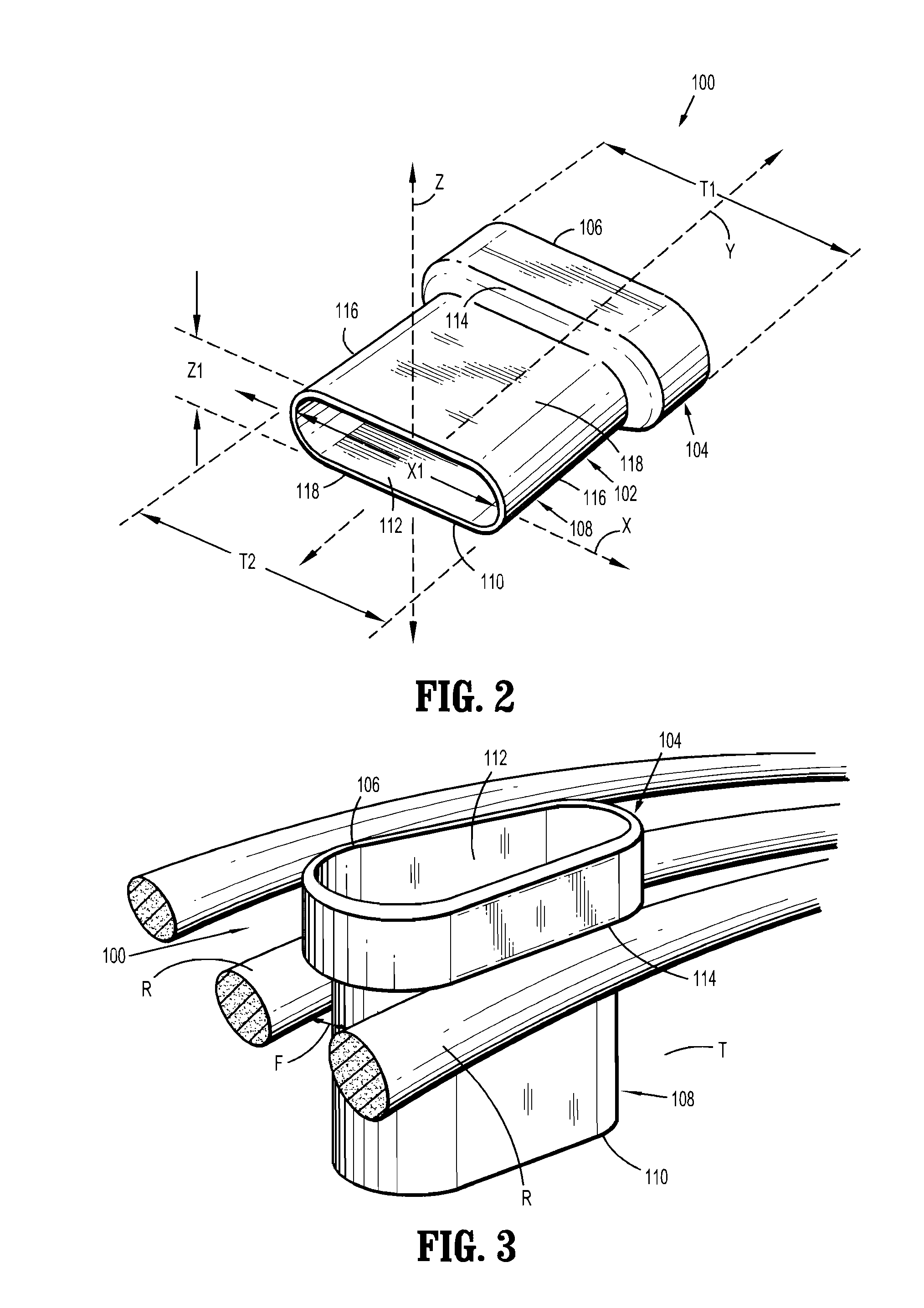
[0011]In one aspect of the present disclosure, a surgical access assembly is disclosed that is configured and dimensioned for positioning within an opening in tissue which provides access to an intercostal space defined between a patient's adjacent ribs in order to facilitate the passage of a surgical instrument into an internal work site. The body portion has an inner liner formed from a first material and defining an internal space that is configured and dimensioned to removably receive the surgical instrument, and an outer liner that is positioned about the inner liner. The outer liner is formed from a second material having a lower durometer than the first material such that the outer liner is resiliently deformable to facilitate conformity with the intercostal space to minimize the application of force to the patient's tissue upon insertion and removal of the access assembly and manipulation of the surgical instrument within the internal space.
[0013]The surgical access assembly may include a body portion with a proximal portion that defines a first transverse dimension, and a distal portion that defines a second, smaller transverse dimension. The configuration and dimensions of the proximal portion facilitate engagement with the patient's tissue to prevent passage of the access assembly entirely into the internal work site.
[0019]The step of inflating the access assembly may include causing a proximal portion thereof to define a first transverse dimension greater than a second transverse dimension defined by a distal portion thereof such that the proximal portion is configured and dimensioned for engagement with the patient's tissue to prevent passage of the access assembly entirely into the internal work site.

Problems solved by technology

However, reducing patient trauma during the procedure, discomfort during recovery, and the overall recovery time remain issues of importance.

Method used


Image

  • Surgical access assembly
  • Surgical access assembly
  • Surgical access assembly

Examples


Embodiment Construction

[0032]Various embodiments of the presently disclosed access assembly, and methods of using the same, will now be described in detail with reference to the drawings wherein like references numerals identify similar or identical elements. In the drawings, and in the following description, the term “proximal” should be understood as referring to the end of the access assembly, or component thereof, that is closer to the clinician during proper use, while the term “distal” should be understood as referring to the end that is farther from the clinician, as is traditional and conventional in the art. Additionally, use of the term “tissue” herein below should be understood to encompass both the patient's ribs, and any surrounding tissues.

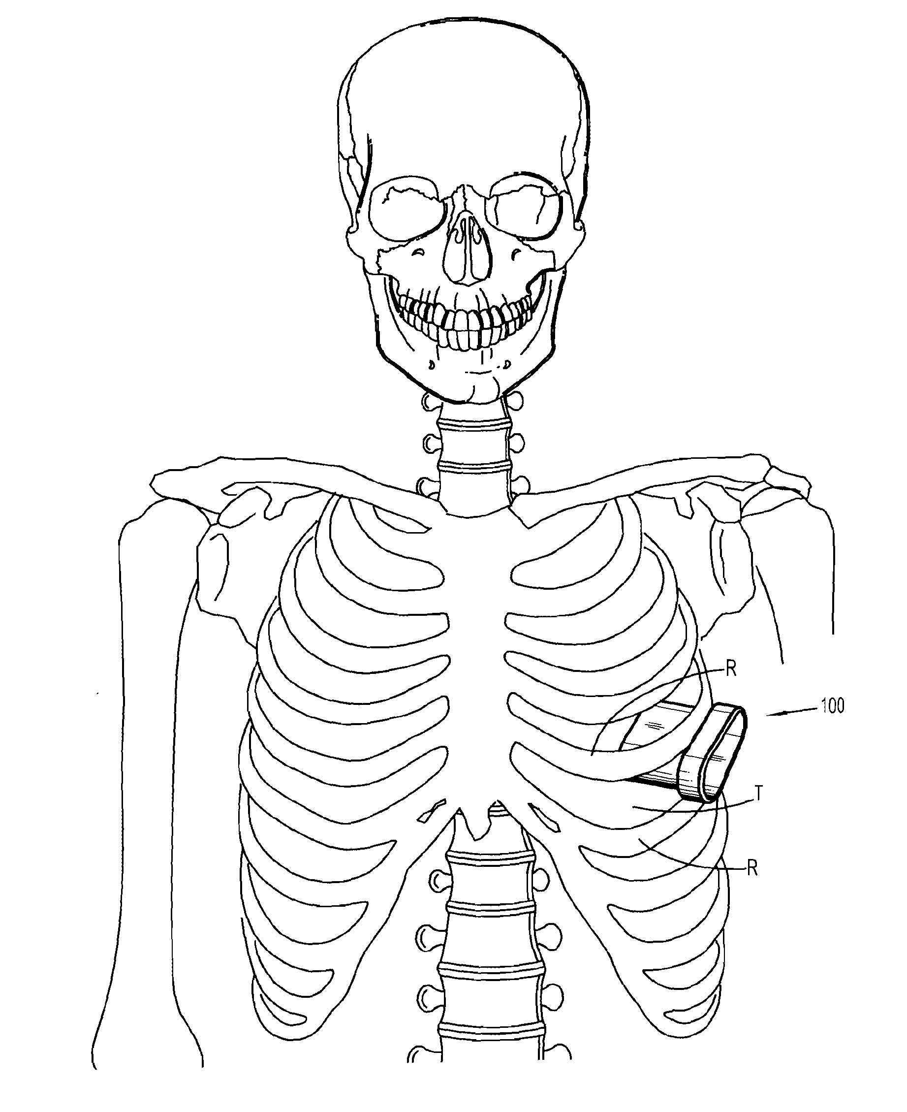
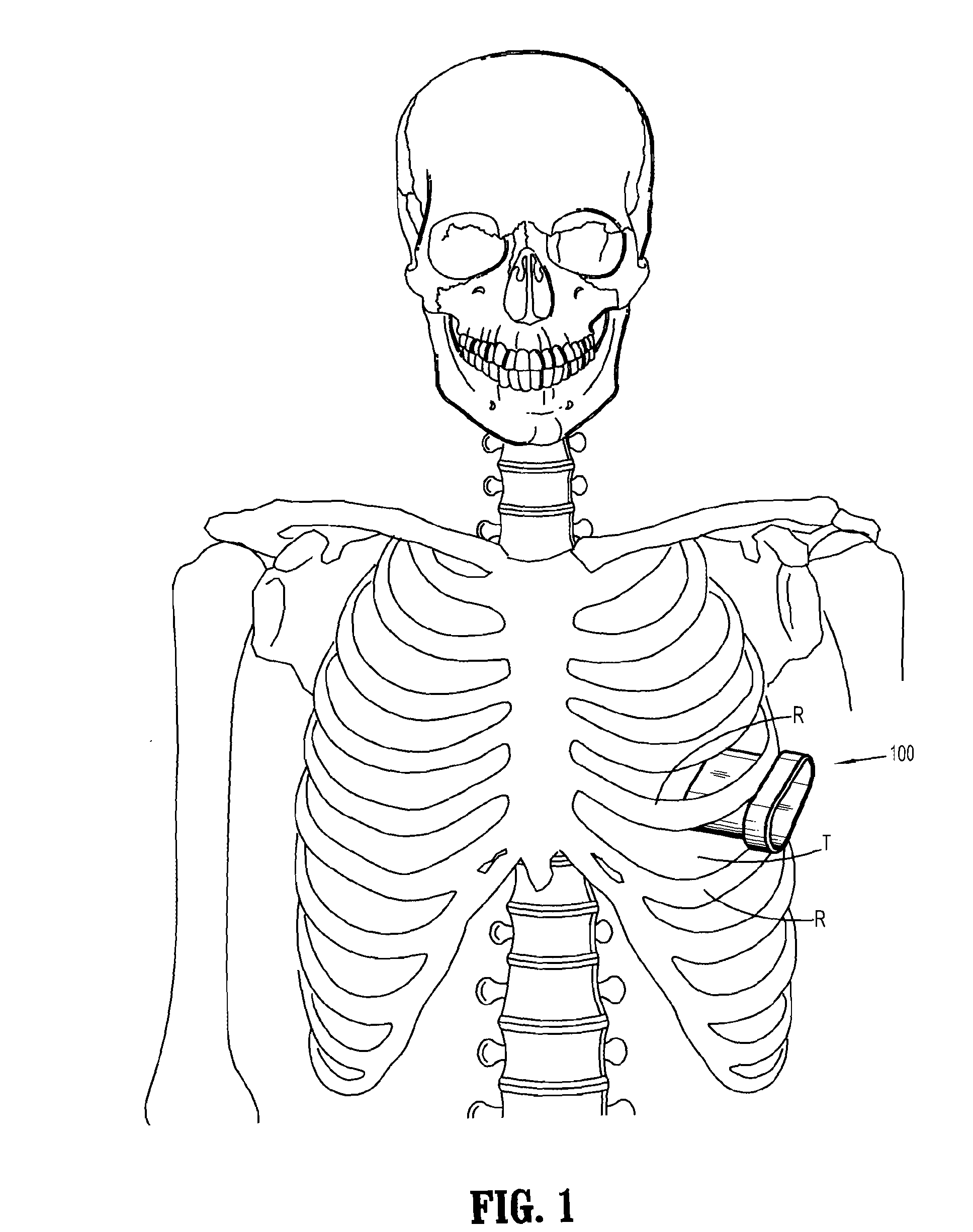
[0033]FIGS. 1-4 illustrate one embodiment of the presently disclosed surgical access assembly, which is identified by the reference character 100, in use during the course of a minimally invasive thoracic surgical procedure. As such, in the embodiment of t...


PUM


Abstract

A surgical access assembly configured and dimensioned for positioning within an intercostal space defined between a patient's adjacent ribs to facilitate passage of a surgical instrument into an internal work site. The surgical access assembly includes a body portion that may be either partially or wholly formed from a resilient material such that the surgical access assembly is resiliently deformable to facilitate conformity with the intercostal space in order to minimize the application of force to the patient's tissue upon insertion and removal of the access assembly and manipulation of the surgical instrument.

Description

CROSS-REFERENCE TO RELATED APPLICATIONS[0001]This application claims the benefit of U.S. Provisional Patent Application No. 61 / 107,749, filed on Oct. 23, 2008, the entire contents of which are incorporated by reference herein.BACKGROUND[0002]1. Technical Field[0003]The present disclosure relates generally to devices and techniques for performing minimally invasive surgical procedures. More particularly, the present disclosure relates to a device that is configured and dimensioned for positioning within an intercostal space to facilitate access to an internal surgical work site with one or more surgical instruments.[0004]2. Background of the Related Art[0005]In an effort to reduce trauma and recovery time, many surgical procedures are performed through small openings in the skin, such as an incision or a natural body orifice. For example, these procedures include laparoscopic procedures and thoracic procedures, such as those that are performed to investigate, diagnose, and treat dise...

Claims


Application Information

Patent Timeline
Patent Type & Authority Applications(United States)
IPC IPC(8): A61B1/32
CPCA61B17/3421A61B17/3423A61B2017/00557A61B2017/00862A61B2017/0237A61B2017/3427A61B2017/3429
Inventor WENCHELL, THOMASRACENET, DAVID C.CENICCOLA, ANTHONY L.RACENET, DANYEL J.NEAVE, NADIA F.BETTUCHI, MICHAEL J.UZNANSKI, MARGARETMARTIN, KIMBERLY E.LEACH, JOHNHAIG, FIONA M.COLLIER, NICHOLAS JOHNFLEMING, ALISTAIRO'PREY, CORMAC
Owner TYCO HEALTHCARE GRP LP
Learn More