Communication device, communication system, position detection method and program

a communication system and position detection technology, applied in the direction of measurement devices, multi-channel direction-finding systems using radio waves, instruments, etc., can solve the problems of increasing circuit scale and cost, and achieve the effect of accurately measuring the position of the devi

Active Publication Date: 2010-07-08
SONY CORP
View PDF4 Cites 6 Cited by
  • Summary
  • Abstract
  • Description
  • Claims
  • Application Information

AI Technical Summary

Benefits of technology

[0018]According to the embodiments of the present invention described above, it is possible to provide a communication device, a communication system, a positio

Problems solved by technology

However, according to the technique disclosed in U.S. Pat. No. 6,824,480, it is necessary to mount a larg

Method used


Image

  • Communication device, communication system, position detection method and program
  • Communication device, communication system, position detection method and program
  • Communication device, communication system, position detection method and program

Examples


Embodiment Construction

)

[0030]Hereinafter, preferred embodiments of the present invention will be described in detail with reference to the appended drawings. Note that, in this specification and the appended drawings, structural elements that have substantially the same function and structure are denoted with the same reference numerals, and repeated explanation of these structural elements is omitted.

[0031]A preferred embodiment of the present invention will be described hereinafter in the following order.

[0032]1. Overview of Communication System according to Embodiment

[0033]2. Explanation of Configuration of Device[0034]2-1. Configuration of Transmitting Device[0035]2-2. Configuration of Receiving Device

[0036]3. Range Estimation Processing (First Stage)

[0037]4. Position Determination Processing (Second Stage)

[0038]5. Flow of Processing

[0039]6. Summary

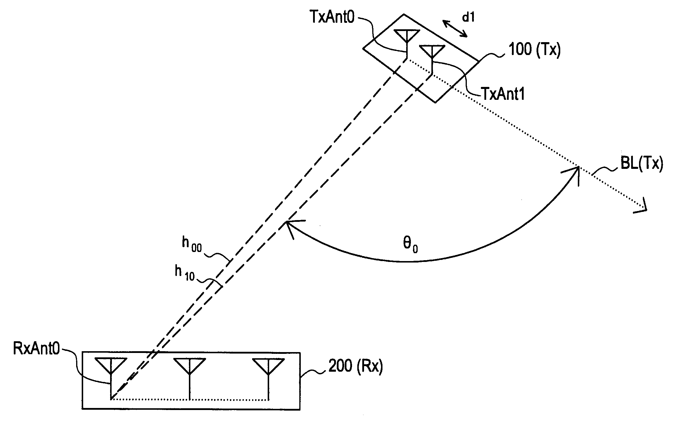
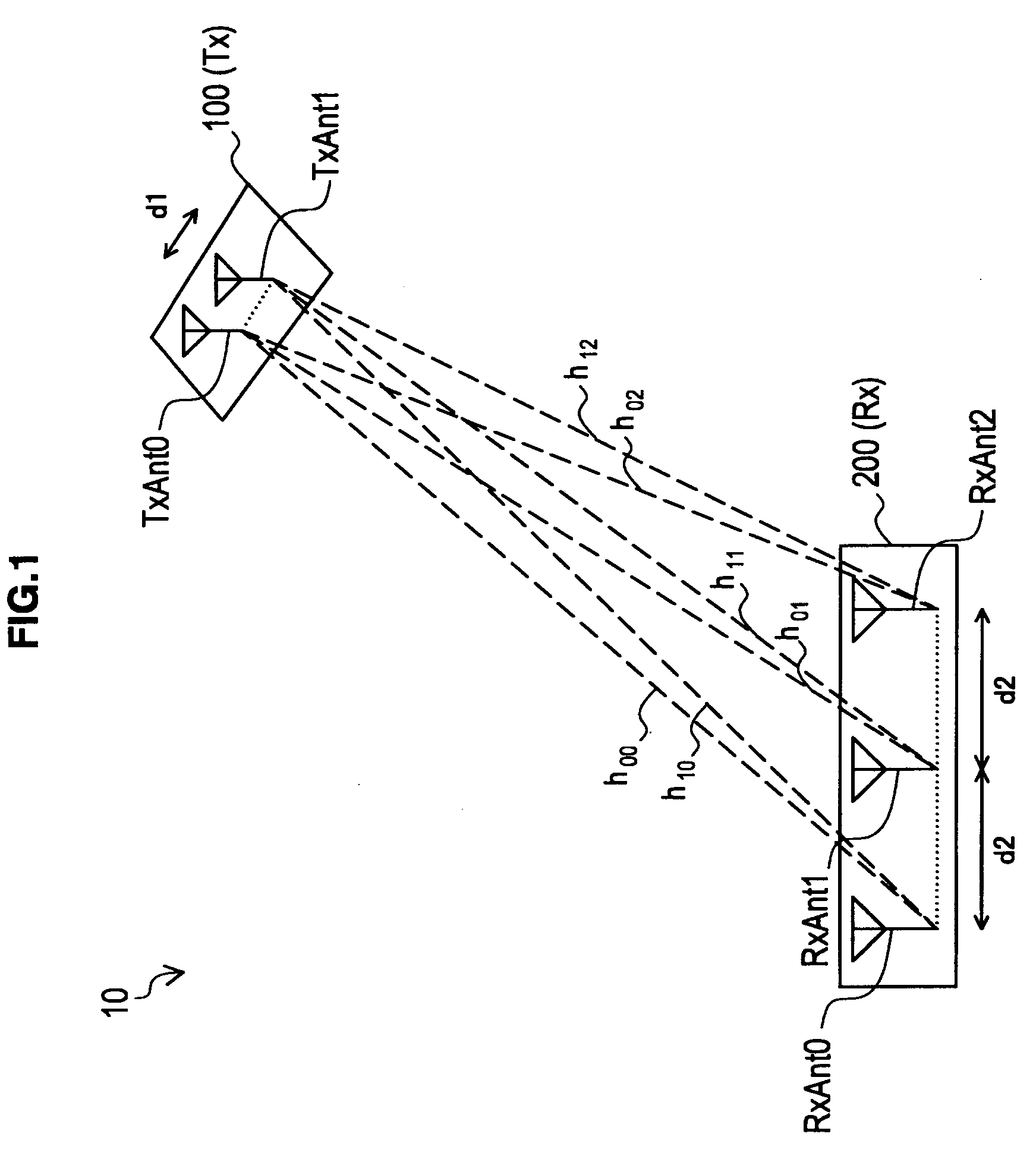
[0040]An overview of a communication system 10 according to an embodiment of the present invention is described firstly.

[0041]FIG. 1 is a view schematical...


PUM


Abstract

There is provided a communication device including: a receiving unit that receives radio signals transmitted from another communication device using a plurality of transmitting antennas by a plurality of receiving antennas; an estimation unit that estimates a range of a position where said another communication device possibly exists based on a phase of each radio signal received by the receiving unit and antenna spacing between the transmitting antennas; and a position determination unit that determines an existing position of said another communication device within the range estimated by the estimation unit.

Description

BACKGROUND OF THE INVENTION[0001]1. Field of the Invention[0002]The present invention relates to a communication device, a communication system, a position detection method and a program.[0003]2. Description of the Related Art[0004]Various techniques have been proposed that detect a position of a device of its own or a device at the other end of communication with use of radio signals transmitted or received by radio communication. Among them, a technique that detects a position by using an array antenna is based on the prerequisite that signals arrive at a receiving array as spherical waves. It is thus necessary to lengthen a baseline of the receiving array according to an assumed distance to a signal source. However, if the antenna spacing of the receiving array is a half-wavelength or larger, a grating lobe occurs, which hampers determining a position uniquely.[0005]In order to satisfy such conflicting conditions, U.S. Pat. No. 6,824,480, for example, discloses a technique that p...

Claims


Application Information

Patent Timeline
IPC IPC(8): G01S1/30
CPCG01S3/74G01S5/0221G01S5/12G01S11/04G01S5/02213
Inventor FUKADA, HIROYUKIIZUMI, SEIICHI
Owner SONY CORP
Why Eureka
Try Eureka