
Image display device, control method for an image display device, and adjustment system for an image display device

a technology of image display device and control method, which is applied in the direction of instruments, computing, electric digital data processing, etc., can solve the problems of delay in control, inability to adapt to a characteristic change over time, and the light-emitting luminance of the image display device cannot be kept constant for the same image data, etc., to achieve the effect of stabilizing the light-emitting luminance of the image display devi

Active Publication Date: 2010-07-08
LG DISPLAY CO LTD
View PDF17 Cites 15 Cited by
  • Summary
  • Abstract
  • Description
  • Claims
  • Application Information

AI Technical Summary

Benefits of technology

The present invention provides a technology to stabilize the light-emitting luminance of an image display device. It recognizes a predicted value of a parameter on driving of the pixel circuit based on image data and obtains an actually-measured value of the parameter while causing the light-emitting element to emit light in accordance with the image data. It then compares the predicted value and the actually-measured value and controls the power supply voltage applied to the pixel circuit in response to the comparison result. This ensures that the actually-measured value is within a narrower reference range and stops the increase / decrease of the power supply voltage if a relationship in which the actually-measured value is included in the narrower reference range is satisfied. Overall, this technology helps to stabilize the light-emitting luminance of the image display device.

Problems solved by technology

However, a manner in which temperature of the organic EL panel is measured to adjust luminance with respect to a temperature change thereof is adaptable to a temperature change in an initial state, but is not adaptable to a characteristic change over time due to degradation of the organic EL panel or the like.
That is, the light-emitting luminance of the image display device cannot be kept constant for the same image data when a characteristic of the TFT or the organic EL element changes over time.
Further, when light-emitting is controlled in accordance with a temperature change, there is required a certain length of period for the temperature of the organic EL panel to follow the temperature change after the control, which is likely to result in a delay in control.
The problems as described above are typically common in image display devices in which light-emitting luminance changes due to a characteristic change over time or temperature change.

Method used


Image

  • Image display device, control method for an image display device, and adjustment system for an image display device
  • Image display device, control method for an image display device, and adjustment system for an image display device
  • Image display device, control method for an image display device, and adjustment system for an image display device

Examples


modification 1

[0095](Modification 1)

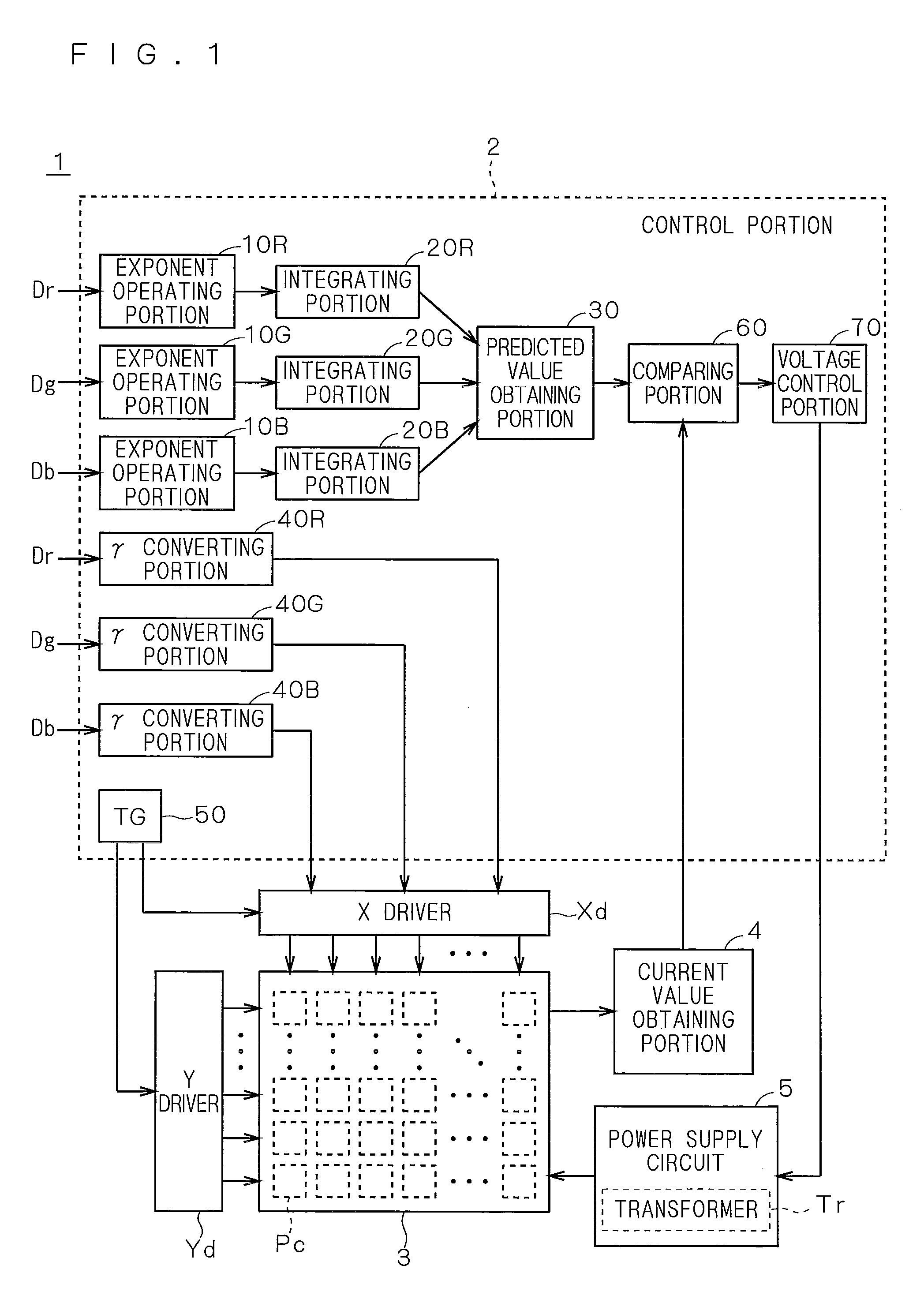
[0096]In the embodiment described above, the power supply voltage is adjusted until the actually-measured current consumption Ir reaches the second reference range R2 with the predicted current consumption Ip being as the center. However, the present invention is not limited thereto.

[0097]For example, the power supply voltage may be adjusted until the actually-measured current consumption Ir reaches the predicted current consumption Ip. Specifically, the power supply voltage may be reduced until the actually-measured current consumption Ir is equal to or lower than the predict current consumption Ip if the actually-measured current consumption Ir is higher than the predicted current consumption Ip, and may be increased until the actually-measured current consumption Ir is equal to or higher than the predicted current consumption Ip if the actually-measured current consumption Ir is lower than the predicted current consumption Ip.

[0098]FIGS. 6 and 7 are diagrams...

modification 2

[0110](Modification 2)

[0111]In the embodiment described above, the exponent operating portions 10R, 10G and 10B substitute the pixel values Dr, Dg and Db for an exponential function, to thereby calculate the values iR, iG and iB, which are obtained by raising the pixel values Dr, Dg and Db of the respective colors to the 2.2-th power, one by one, but the present invention is not limited thereto. For example, a storing portion or the like may store a data table (hereinafter, abbreviated to “table”) in which the pixel values Dr, Dg and Db to be input and the values iR, iG and iB obtained by raising the pixel values Dr, Dg and Db to the 2.2-th power are associated with each other, and values obtained by raising the pixel values of the respective colors to the 2.2-th power may be obtained by referring to that table.

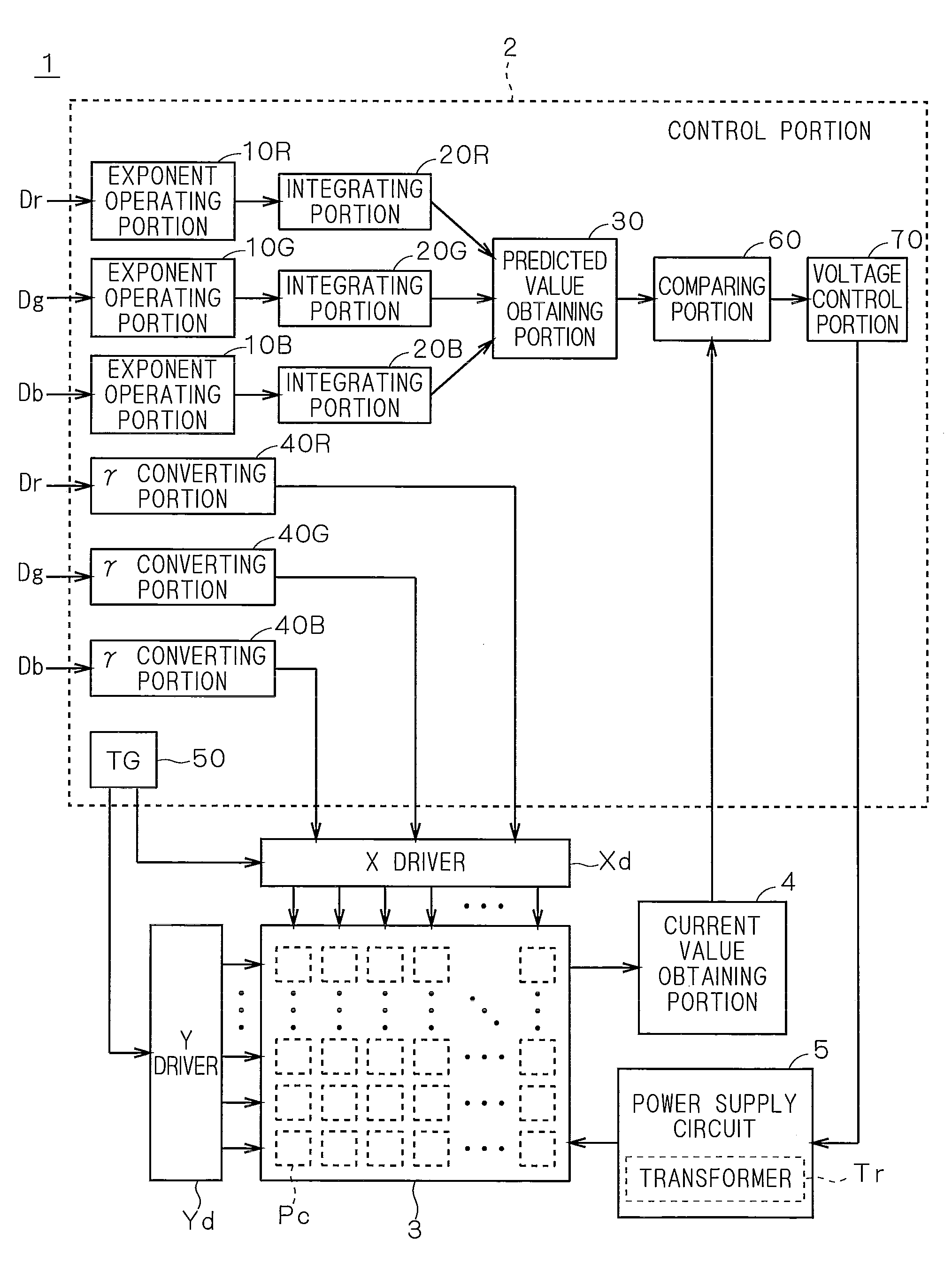
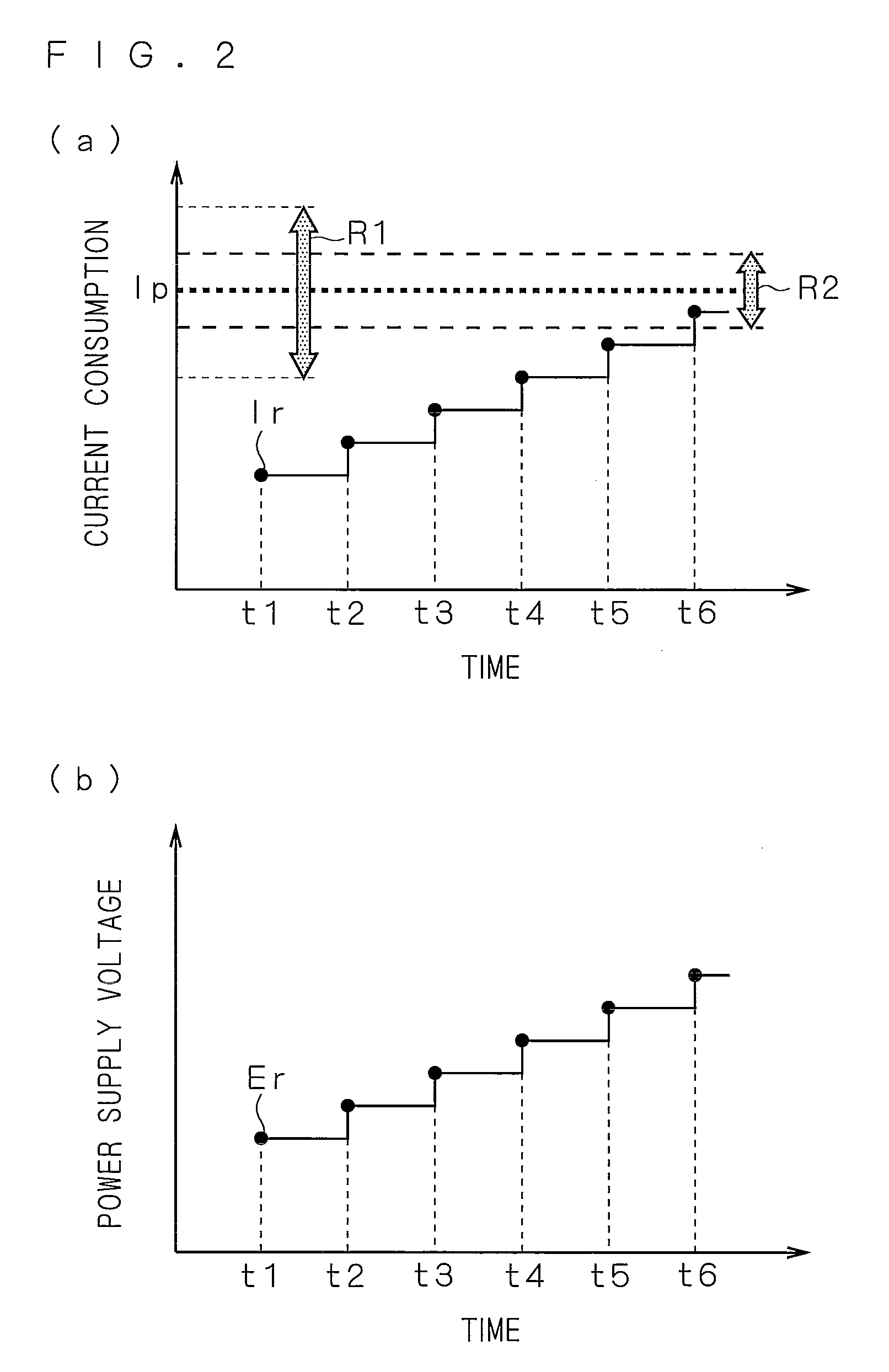
[0112]FIG. 9 is a block diagram showing a functional structure of an image display device 1A according to Modification 2. The image display device 1A is different from the im...

modification 3

[0120](Modification 3)

[0121]In Modification 1 described above, the power supply voltage of the organic EL panel 3 is controlled in accordance with the comparison result between the predicted current consumption Ip and the actually-measured current consumption Ir, but the present invention is not limited thereto.

[0122]For example, luminance of light emitted from the plurality of light-emitting elements included in the plurality of pixel circuits Pc of the organic EL panel 3 may be set as a parameter. In this case, first, a predicted value of luminance of light emitted from the organic EL panel 3 with respect to certain image data is recognized based on a rule determined in advance. Then, an actual value thereof is obtained, whereby the power supply voltage of the organic EL panel 3 may be controlled in accordance with a comparison result between the predicted value and the actually-measured value.

[0123]With the structure as described above, the power supply voltage is increased / decre...


PUM


Abstract

It is aimed to provide a technology capable of stabilizing light-emitting luminance of an image display device. In order to achieve the above-mentioned object, an image display device includes a pixel circuit including a light-emitting element, a recognizing portion which recognizes a predicted value of a parameter on driving of the pixel circuit based on image data, and an obtaining portion which obtains an actually-measured value of the parameter while causing the light-emitting element to emit light in accordance with the image data. This image display device further includes a comparing portion which compares the predicted value and the actually-measured value with each other, and a control portion which controls a power supply voltage applied to the pixel circuit in accordance with a comparison result of the comparing portion. The control portion increases / decreases, in response to a fact that the actually-measured value falls outside a first reference range with the predicted value being as a reference, the power supply voltage so that the actually-measured value is included in a second reference range which is within the first reference range and is narrower than the first reference range, and stops the increase / decrease of the power supply voltage in a case where a relationship in which the actually-measured value is included in the second reference range is satisfied. Note that the control portion may be provided outside the image display device.

Description

TECHNICAL FIELD[0001]The present invention relates to an image display device.BACKGROUND ART[0002]There has been conventionally known an image display device including organic electroluminescence (EL) elements in which electroluminescence is used.[0003]In the image display device as described above, temperature of an organic EL panel changes due to temperature characteristics of a thin film transistor (TFT) and the organic EL element, and accordingly light-emitting luminance changes.[0004]Therefore, there is proposed a technology of appropriately controlling a signal waveform, signal voltage or power supply voltage to be provided to a pixel circuit of an organic EL element to stabilize light-emitting luminance with respect to a temperature change of an organic EL panel in a wide temperature range (for example, from −20° C. to +60° C.) (for example, Japanese Patent Application Laid-Open No. 07-263142, Japanese Patent Application Laid-Open No. 2000-214824, Japanese Patent Application ...

Claims


Application Information

Patent Timeline
Patent Type & Authority Applications(United States)
IPC IPC(8): G06F3/038
CPCG09G3/3208G09G2320/041G09G2320/043G09G2330/02G09G2360/145G09G2360/16G09G3/20G09G3/30
Inventor KOBAYASHI, YOSHINAO
Owner LG DISPLAY CO LTD
Features
  • Generate Ideas
  • Intellectual Property
  • Life Sciences
  • Materials
  • Tech Scout
  • Unparalleled Data Quality
  • Higher Quality Content
  • 60% Fewer Hallucinations
Learn More