Display clip system and timing clip control method thereof

a technology of liquid crystal panel and display clip, which is applied in the field of display clip system and timing control method of liquid crystal panel, can solve the problems of deteriorating screen transient flickering, inconsistent charging charge of liquid crystal unit, and inconvenient operation, so as to avoid screen transient flickering, avoid additional design and production costs, and stable imaging luminance

Inactive Publication Date: 2012-05-03
CHUNGHWA PICTURE TUBES LTD
View PDF0 Cites 19 Cited by
  • Summary
  • Abstract
  • Description
  • Claims
  • Application Information

AI Technical Summary

Benefits of technology

[0012]The characteristics of the present invention are as follows. In a clip system disclosed by the present invention, when system input signals of different frame rates are obtained, base working signals carrying the same clip voltage and having the same trigger time length are still provided, so that a charging time length and charging charges of a liquid crystal unit that receives the base working signal for charging remain the same before and after the frame rate switches, thus steadyin

Problems solved by technology

When each of the arranged liquid crystal units is charged, the base working signal is affected by electric impedance caused by the liquid crystal units of a increasing number and through which the base working signal passes, such that a waveform of the base working signal deforms gradually, thus resulting in inconsistent charging charges of the liquid crystal units in the process.
However, after the frame rate is switched, the

Method used


Image

  • Display clip system and timing clip control method thereof
  • Display clip system and timing clip control method thereof
  • Display clip system and timing clip control method thereof

Examples


Embodiment Construction

[0018]Preferred embodiments of the present invention are described below in detail with reference to the accompanying drawings.

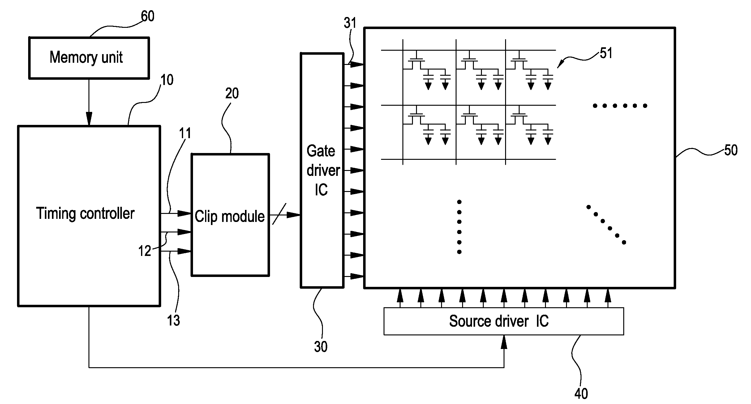
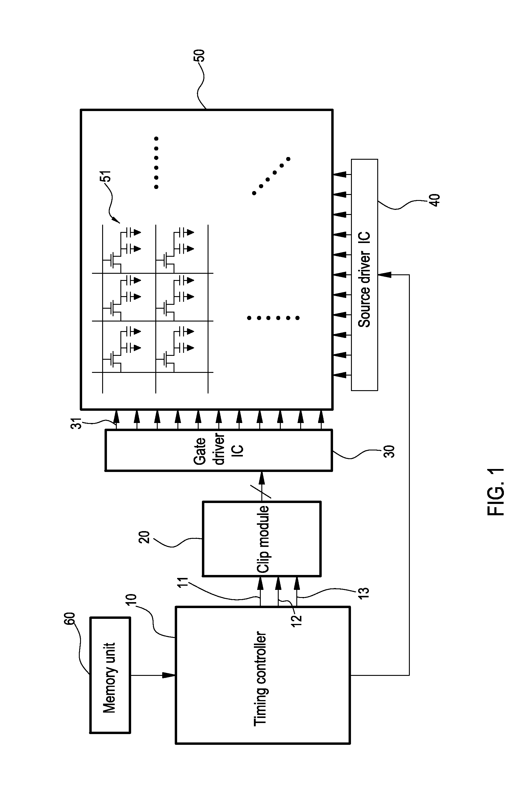
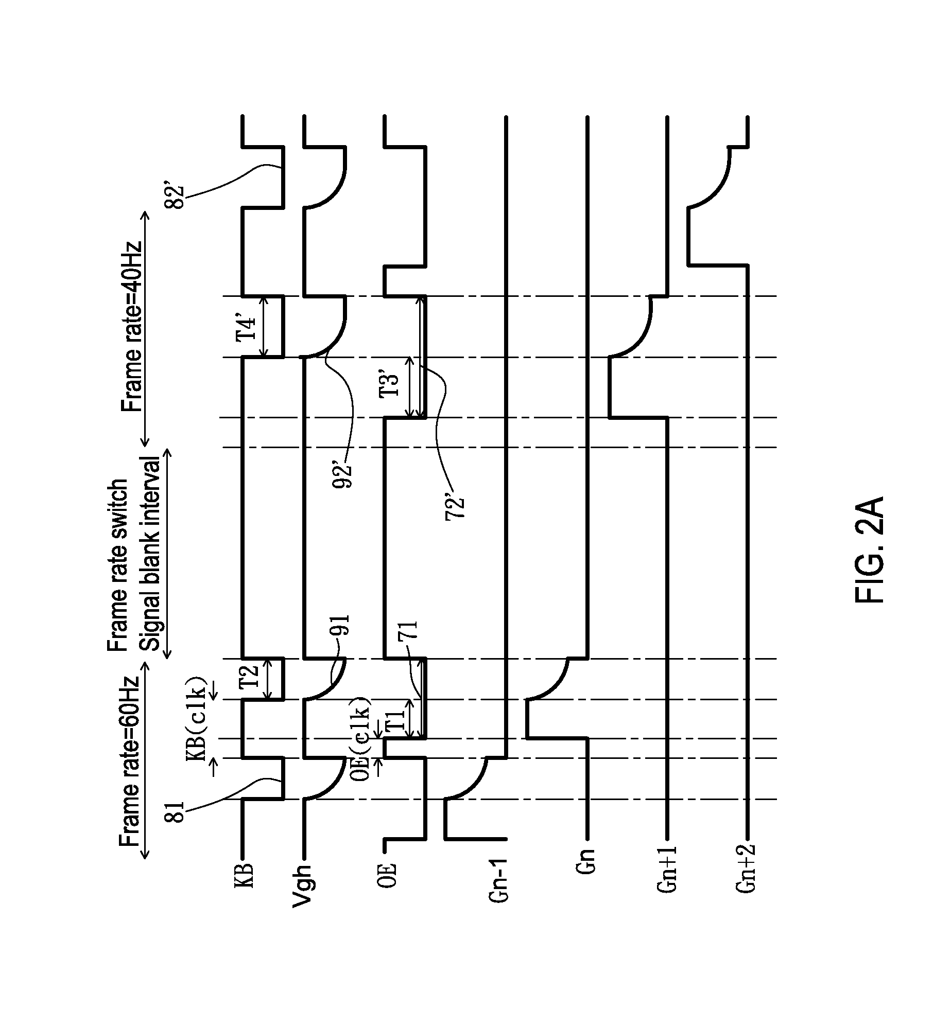
[0019]Referring to FIG. 1, a schematic structural view of a clip system according to an embodiment of the present invention is shown. Referring to FIG. 2A and FIG. 2B together, it should be noted that, a liquid crystal panel is taken as an example in the following embodiments, but the techniques disclosed by the present invention are applicable to liquid crystals, OLEDs, and any other type of active matrix displays, and are not limited to the liquid crystal displays and liquid crystal panels.

[0020]The system includes a timing controller 10 and a clip module 20. The timing controller 10 is electrically connected to the clip module 20, and the clip module 20 is electrically connected to a gate driver circuit 30 of a liquid crystal panel 50. The timing controller 10 is also connected to multiple source driver circuits 40 to provide a pixel data signal to the so...


PUM


Abstract

A display clip system and a timing clip control method thereof are provided. The clip system is connected to a gate driver circuit, and includes a timing controller and a clip module. According to a system input signal and it's frame rates, the timing controller generates an enable signal, a clip trigger signal, and a base working signal. The clip module adjusts the base working signal by using the enable signal and the clip trigger signal. Then, the base working signal carries a first clip voltage to output to the gate driver circuit. When the frame rate changes, the timing controller adjusts trigger points and trigger time lengths of the enable signal and the clip trigger signal, and the clip module adjusts the base working signal. Then, the base working signal carries a second clip voltage equal to the first clip voltage to output to the gate driver circuit.

Description

CROSS-REFERENCE TO RELATED APPLICATION[0001]This application claims the benefit of Taiwan Patent Application No. 099137210, filed on Oct. 29, 2010, which is hereby incorporated by reference for all purposes as if fully set forth herein.BACKGROUND OF THE INVENTION[0002]1. Field of Invention[0003]The present invention relates to a timing controller and a timing control method of a liquid crystal panel, and more particularly to a clip system and a timing clip control method, capable of providing a base working signal and a clip voltage of the same signal information before and after a frame rate of a system signal changes.[0004]2. Related Art[0005]Currently, requirements of energy saving of electronic devices have become one of major criteria in design performed by manufacturers, which is also true to active matrix displays, such as liquid crystal displays and Organic Light-Emitting Diode (OLED) displays. Therefore, manufacturers research and develop a method for decreasing power consu...

Claims


Application Information

Patent Timeline
IPC IPC(8): G06F3/038
CPCG06F1/3265G09G3/3648G09G3/3674Y02D10/153G09G2320/0223G09G2340/0435G09G2310/08Y02D10/00
Inventor HSIAO, CHUNG-CHIHHUANG, CHIAO-LIN
Owner CHUNGHWA PICTURE TUBES LTD
Why Eureka
Try Eureka