Light emitting material and light emitting device

a light emitting device and light emitting material technology, applied in the direction of discharge tube luminescnet screen, indium organic compound, organic chemistry, etc., can solve the problems of device luminous efficiency and stability, device device to be produced by an application method cannot provide sufficient performance, etc., to achieve high luminous efficiency, low cost, and high stability

Inactive Publication Date: 2008-01-10
CANON KK
View PDF0 Cites 20 Cited by
  • Summary
  • Abstract
  • Description
  • Claims
  • Application Information

AI Technical Summary

Benefits of technology

[0009]An object of the present invention is to provide a light emitting material of which a light emitting device having high luminous efficiency and high stability and capable of being provided at a low cost can be formed, and a light emitting device using the light emitting material.
[0012]A light emitting device using the light emitting material of the present invention has high luminous efficiency, stably emits light, and is provided at a low cost.

Problems solved by technology

On the other hand, as pointed out in Journal of Polymer Science: Part B: Polymer Physics 41, 2681-2690 (2003), a device to be produced by an application method cannot provide sufficient performance when the light emitting layer of the device is formed of two kinds of materials, that is, an iridium coordination compound and a host material.
In other words, owing to, for example, a problem of compatibility between both materials and a difference in solubility in a solvent between the materials, a phenomenon such as the inhibition of light emission by the agglomeration of the iridium coordination compound in the device occurs, so the device is problematic in terms of luminous efficiency and stability at the time of driving, and hence cannot provide sufficient performance.
However, the external quantum efficiency of a device using such compound is as low as 1.5% at best.
An influence of the substituent increases the number of deactivation paths to reduce the luminous efficiency of the device.
Therefore, no phosphorescent dopant suitable for an application method has been heretofore found in red light emitting materials, and the development of such dopant has been an object.

Method used


Image

  • Light emitting material and light emitting device
  • Light emitting material and light emitting device
  • Light emitting material and light emitting device

Examples


examples 1 to 6

[0058]Hereinafter, a method of synthesizing each of Exemplified Compound 1001 (Example 1), Exemplified Compound 1002 (Example 2), Exemplified Compound 1003 (Example 3), Exemplified Compound 1004 (Example 4), Exemplified Compound 1007 (Example 5), and Exemplified Compound 1008 (Example 6) will be described.

[0059]The synthesis of each of those compounds follows a general synthesis method involving producing a C—C bond or C—N bond between aryl groups, and employs mainly a Suzuki coupling method based on a reaction between a halide and boric acid using a palladium catalyst.

[0060]First, the following scheme shows a method of synthesizing the intermediate of an oligofluorenyl group involving sequentially coupling fluorene groups by Suzuki coupling.

[0061]The following schemes each show a scheme in which a phenylisoquinoline skeleton and an oligofluorenyl group are bonded to each other. The ligands of Exemplified Compounds 1001 and 1004 can be synthesized by the schemes. 1H-NMR is employed ...

examples 7 to 9

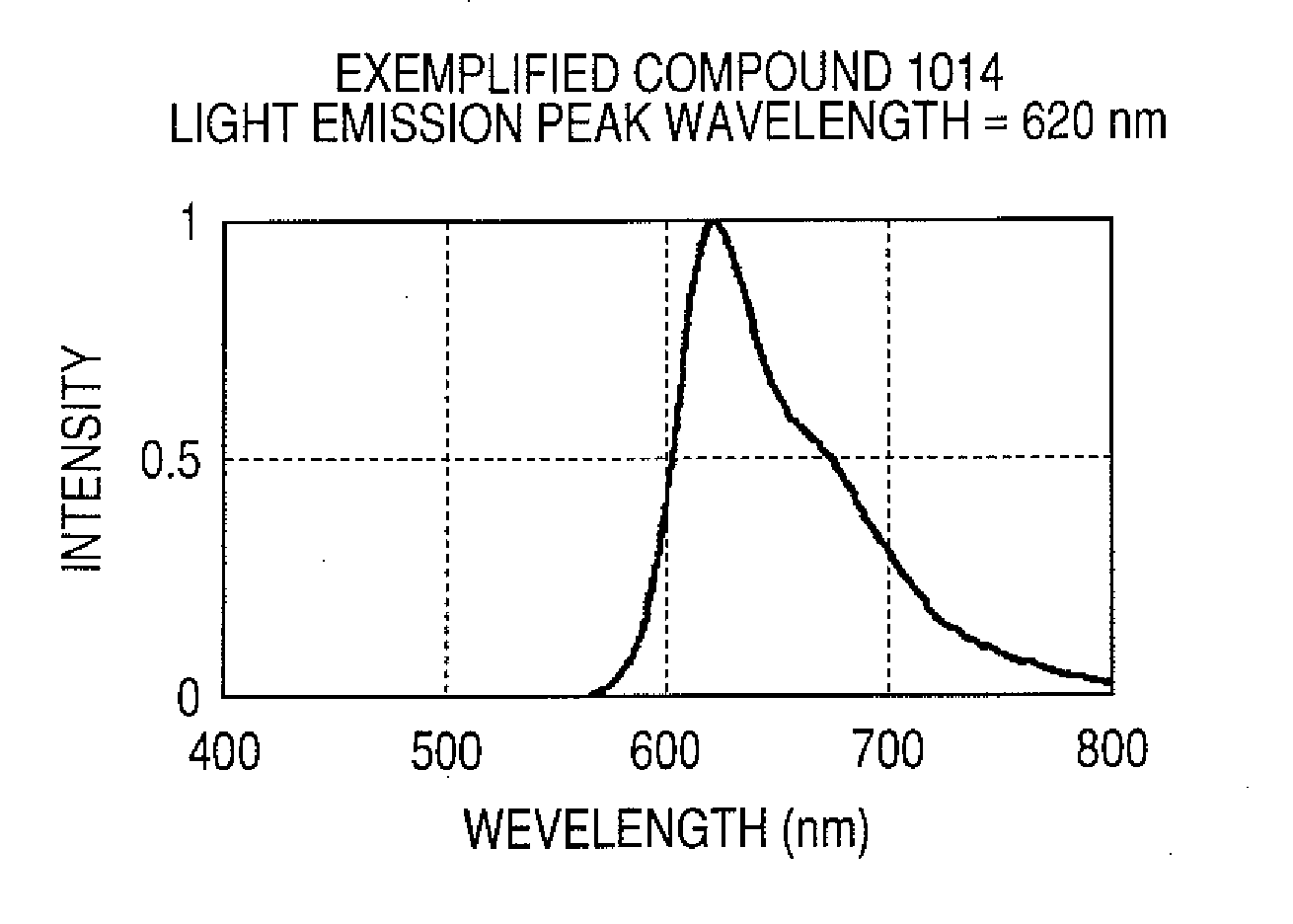
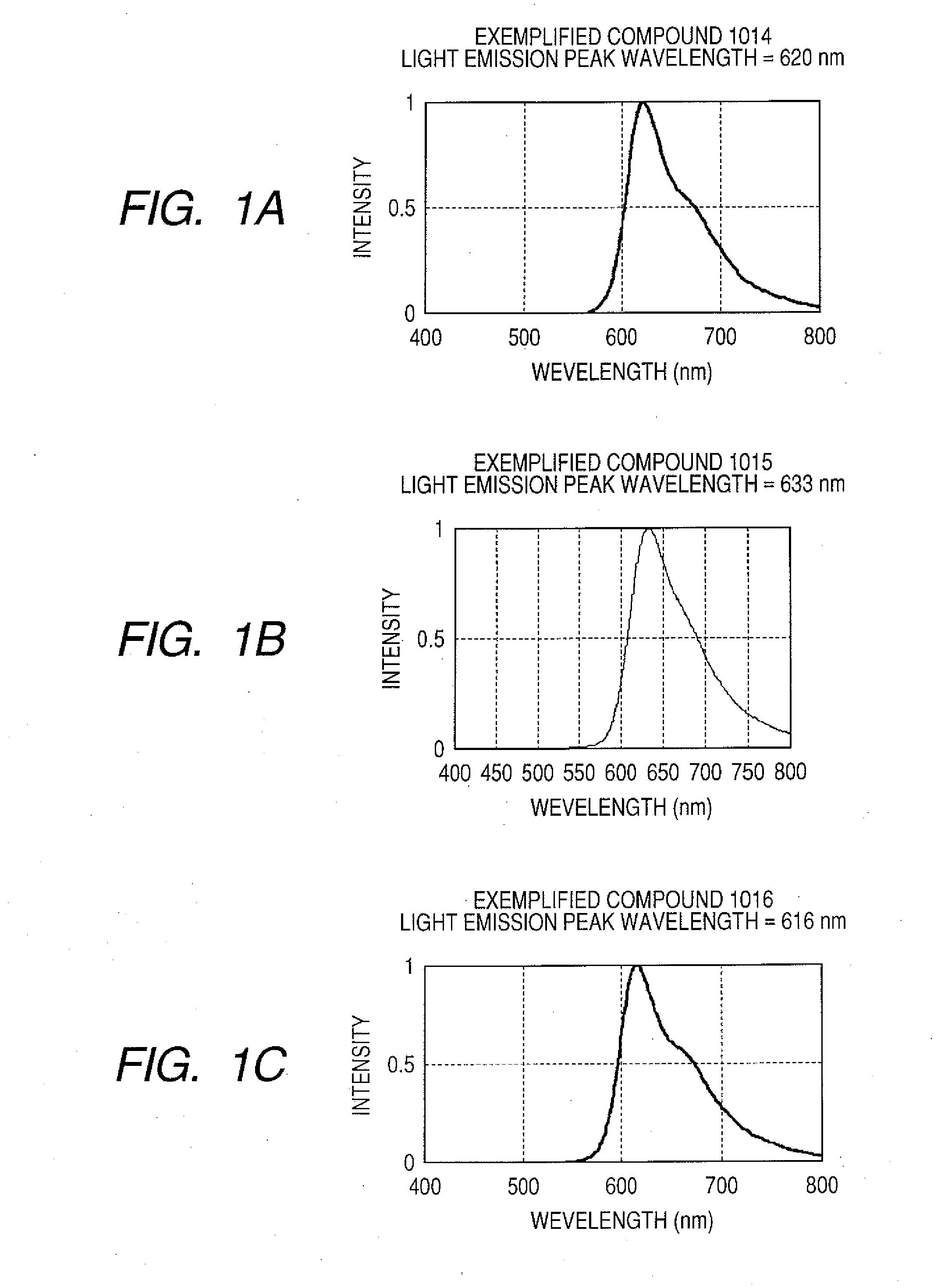
[0064]These examples are synthesis examples of Exemplified Compound 1014 (Example 7), Exemplified Compound 1015 (Example 8), and Exemplified Compound 1016 (Example 9).

[0065]Procedures for synthesizing ligands were shown below. In each procedure, a ligand was synthesized by using a Suzuki coupling reaction, in which a palladium catalyst was used, plural times.

[0066]Iridium complexes were synthesized by using the ligands in accordance with procedures similar to those of Examples 1 to 6.

[0067]The compounds were identified by employing proton NMR and matrix assisted laser desorption / ionization time-of-flight mass spectrometry (MARDI-TOF-MASS) (Autoflex type manufactured by Bruker Daltonics Inc. (Germany)).

[0068]FIGS. 1A to 1C showed the emission spectra of solutions of Exemplified Compounds 1014 to 1016 in toluene. Exemplified Compounds 1014, 1015, and 1016 had light emission peak wavelengths of 620 nm, 633 nm, and 633 nm, respectively, and each emitted pure red light.

examples 10 to 12

[0069]Examples of organic LED devices each using Exemplified Compound 1014, 1015, or 1016 will be described. Each of those complexes can be dissolved well in a xylene solution, and is suitable for an organic EL device to be produced by a spin coating method.

[0070]A device having a constitution including three organic layers was produced. ITO having a thickness of 100 nm was patterned into a circular shape on a glass substrate so that an electrode area would be 3.14 mm2.

[0071]PEDOT (for an organic EL) manufactured by Bayer was applied onto the ITO substrate by spin coating at 1,000 rpm (20 seconds) so as to form a film having a thickness of 40 nm. The resultant was dried in a vacuum chamber at 120° C. for 1 hour.

[0072]The upper portion of the resultant was coated with the following solution by spin coating under a nitrogen atmosphere at 2,000 rpm for 20 seconds, whereby an organic film having a thickness of 60 nm (light emitting layer) was formed. After the formation of the film, the...


PUM

PropertyMeasurementUnit
wavelengthaaaaaaaaaa
external quantum efficiencyaaaaaaaaaa

Abstract

Provided is a light emitting material of which a light emitting device having high luminous efficiency and high stability and capable of being provided at a low cost can be formed. A light emitting material includes the following partial structural formula (1):wherein at least one of R1 to R10 represents a substituent except a hydrogen atom, a total number of benzene ring structures in R1 to R10 is 3 or more, and R1 to R10 include a trifluoromethyl group, or a linear, branched, or cyclic alkyl or alkoxyl group having 2 or more carbon atoms a hydrogen atom of which may be substituted by a halogen atom.

Description

BACKGROUND OF THE INVENTION[0001]1. Field of the Invention[0002]The present invention relates to a light emitting material and a light emitting device using an organic compound, and more specifically, to a light emitting device using a metal coordination compound as a light emitting material.[0003]2. Description of the Related Art[0004]Applied researches have been vigorously conducted on an organic electroluminescence (EL) device because of the potential of the device to function as a light emitting device having high-speed responsiveness and high luminous efficiency (Macromol. Symp., 1997, 125, 1-48). Among the research, a wide range of researches on an iridium metal coordination compound has been carried out because the compound can function as a light emitting material having high luminous efficiency and high stability when used in an organic EL device (Inorganic. Chemistry. 2001, 40, 1704-1711, Journal. American. Chemical. Society. 2001, 123, 4304-4312, International Publication...

Claims


Application Information

Patent Timeline
Patent Type & Authority Applications(United States)
IPC IPC(8): H01J1/63C07D217/02
CPCC07F15/0033C09K11/06C09K2211/1029C09K2211/185H05B33/20H01L51/0037H01L51/0039H01L51/0085H05B33/14H01L51/0003H10K71/12H10K85/1135H10K85/115H10K85/342
Inventor TSUBOYAMA, AKIRASUZUKI, KOICHIWATANABE, TAIKIUENO, KAZUNORI
Owner CANON KK
Why Eureka
Try Eureka