Vehicle braking/driving force control apparatus

a technology of braking/driving force and control apparatus, which is applied in the direction of braking systems, instruments, analogue processes for specific applications, etc., can solve the problem of not being able to control the braking/driving force of each wheel, and achieve the effect of increasing the magnitude of the magnitud

Inactive Publication Date: 2010-07-08
TOYOTA JIDOSHA KK
View PDF4 Cites 34 Cited by
  • Summary
  • Abstract
  • Description
  • Claims
  • Application Information

AI Technical Summary

Benefits of technology

[0016]In the above-mentioned configurations, the means for correcting the target yaw moment may correct the target yaw moment so as to increase the magnitude thereof when the weight of the whole vehicle is great, compared to the case where the weight of the whole vehicle is small.
[0017]In the above-mentioned configurations, the means for correcting the target yaw moment may correct the target yaw moment so as to increase the magnitude thereof when the degree of the deviation of the position of the center of gravity close to the rear wheels is great, compared to the case where the degree of the deviation of the position of the center of gravity close to the rear wheels is small.

Problems solved by technology

However, it cannot control the braking / driving force of each wheel so as to apply the optimum yaw moment to the vehicle according to the boading condition or loading condition or turning condition of the vehicle.

Method used


Image

  • Vehicle braking/driving force control apparatus
  • Vehicle braking/driving force control apparatus
  • Vehicle braking/driving force control apparatus

Examples


first embodiment

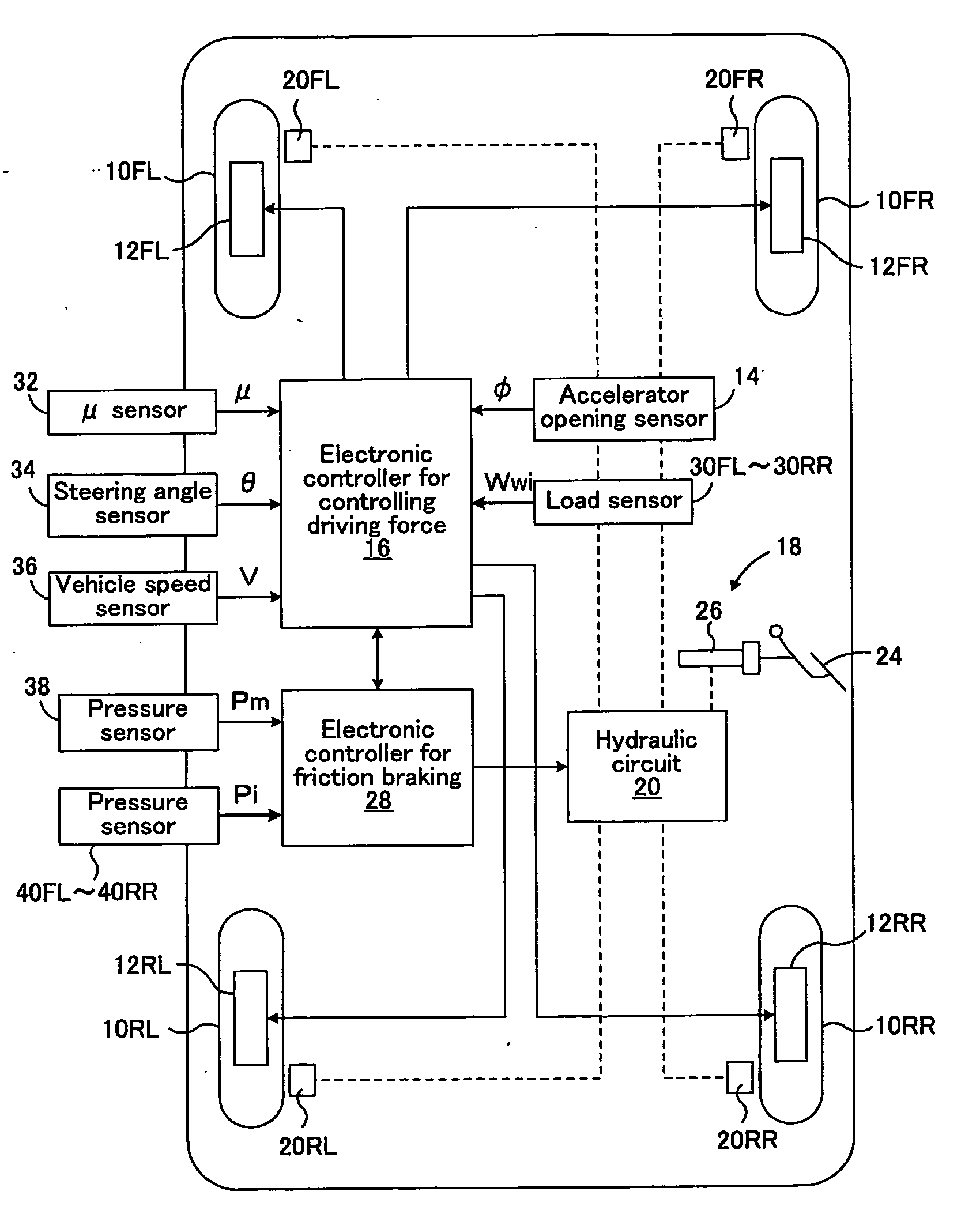
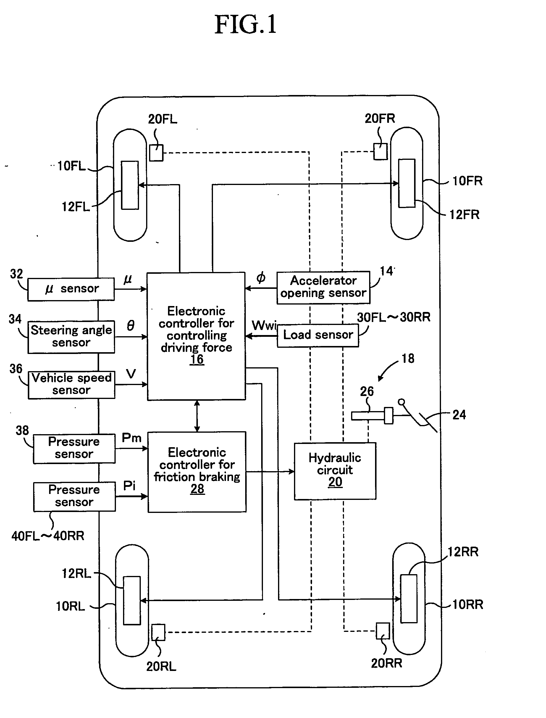
[0049]FIG. 1 is a schematic block diagram showing a braking / driving force control apparatus applied to a right-hand four-wheel drive vehicle of a wheel-in-motor type according to a first embodiment of the present invention.

[0050]In FIG. 1, numerals 10FL and 10FR respectively represent left and right front wheels that are steering wheels, and numerals 10RL and 10RR respectively represent left and right rear wheels that are non-steering wheels. Electric motor generators 12FL and 12FR that are in-wheel motors are incorporated into the left and right front wheels 10FL and 10FR respectively, whereby the left and right front wheels 10FL and 10FR are driven by the electric motor generators 12FL and 12FR. The electric motor generators 12FL and 12FR also function as regenerative electric generators for each of the left and right front wheels upon the braking, so that they generate regenerative braking force.

[0051]Similarly, electric motor generators 12RL and 12RR that are in-wheel motors are...

second embodiment

[0101]FIG. 8 is a schematic block diagram showing a braking / driving force control apparatus applied to a right-hand four-wheel drive vehicle in which driving force and regenerative braking force from a single electric motor generator, which is common to four wheels, are controlled so as to be distributed to front and rear wheels and right and left wheels according to a second embodiment of the present invention. The components in FIG. 8 same as those in FIG. 1 are identified by the same numerals in FIG. 1.

[0102]In this second embodiment, an electric motor generator 40 is provided that serves as a driving source common to the front left wheel 10FL, front right wheel 10FR, rear left wheel 10RL, and rear right wheel 10RR. The driving force and the regenerative braking force from the electric motor generator 40 is transmitted to a front-wheel propeller shaft 44 and rear-wheel propeller shaft 46 through a center differential 42 that can control the distribution ratio to the front wheels ...


PUM


Abstract

A vehicle target braking/driving force and a vehicle target yaw moment to be achieved by a control of braking/driving force of each wheel are-calculated. The target yaw moment is corrected, for example, so as to coincide with the product of the correction coefficient determined based upon, the weight of the whole vehicle, the longitudinal and lateral distribution ratios of wheel vertical loads, and vehicle turning direction, and the target yaw moment, whereby the target yaw moment is corrected in accordance with the weight of the whole vehicle, the position of center of gravity of the whole vehicle, and vehicle turning direction. The final target braking/driving force and target yaw moment that can be achieved by the control of the braking/driving force of each wheel are calculated on the basis of the target braking/driving force and the target yaw moment after the correction, and the braking/driving force of each wheel is controlled so as to achieve the final target braking/driving force and target yaw moment.

Description

TECHNICAL FIELD[0001]The present invention relates to a vehicle braking / driving force control apparatus, and more particularly to a vehicle braking / driving force control apparatus that controls braking / driving force of each wheel.BACKGROUND ART[0002]As one of braking / driving force control apparatuses for a vehicle, such as an automobile, for controlling braking / driving force of each wheel, there has conventionally been known a driving force control apparatus for controlling driving force of each wheel according to a vertical load of each wheel, as disclosed in the Japanese Patent No. 2795445, for example. This braking / driving force control apparatus can enhance running stability of a vehicle compared to the case where the driving force of each wheel is not controlled according to the vertical load of each wheel.[0003]It is considered that, in order to further enhance running stability of a vehicle that can control braking / driving force of each wheel, vehicle braking / driving force an...

Claims


Application Information

Patent Timeline
Patent Type & Authority Applications(United States)
IPC IPC(8): B60T8/1755B60L15/20B60W10/04B60W10/08B60W10/18B60W10/184B60W30/00B60W30/02B60W30/045
CPCB60T8/1755Y02T10/7258B60T2270/613B60W10/12B60W10/184B60W30/02B60W30/045B60W40/064B60W40/11B60W40/112B60W40/114B60W2040/1307B60W2040/1315B60W2040/1346B60W2720/14B60T2250/02Y02T10/72
Inventor URAGAMI, YOSHIOMAEDA, YOSHINORITSUCHIDA, MICHITAKAYOSHIZUE, KENSUKEOKUMURA, KAZUYAANDO, SATOSHISUGIYAMA, KOJI
Owner TOYOTA JIDOSHA KK
Why Eureka
Try Eureka